
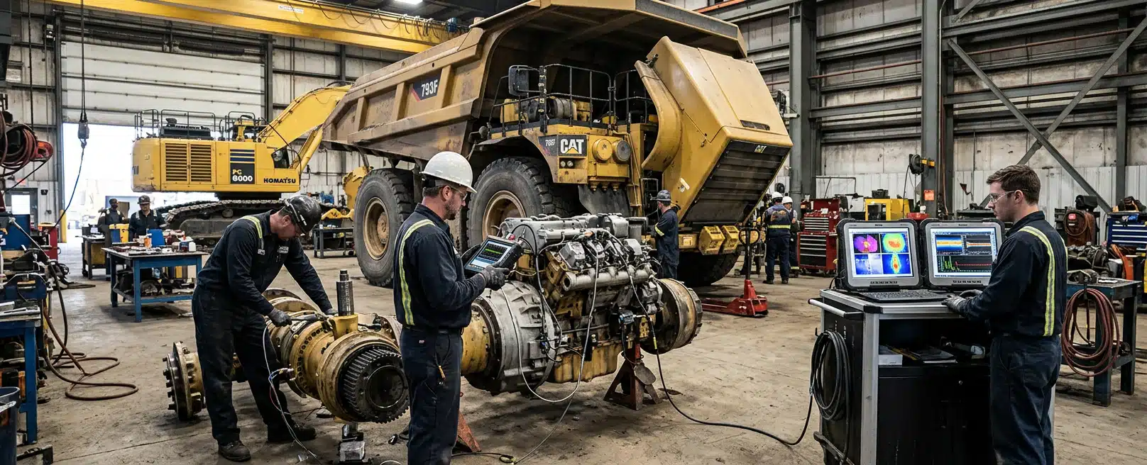
A mining fleet problem is not automatically a vibration job or a structural job. You need to know whether the complaint is a changing mechanical signature, a part that is running out of strength, or both, before anyone writes the next shutdown.
We work on machinery, heavy vehicles and mobile equipment. We measure and interpret vibration, run structural simulation, and capture field or workshop data so the recommendation stands on the machine you actually have.
The useful output is a priority the crew can act on: inspect this, change that mount, capture the missing geometry, or wait only where site risk criteria allow it.
What Vibration Measurement Can Answer
Baselines Against Real Duty
Vibration measurement is a condition method. It records how a machine shakes at chosen points, under the duty it actually sees, then compares that behaviour with an earlier signature.
The interpretation of those condition trends is vibration data analysis. On a mining fleet that usually means wheel ends and final drives, gear mesh, fans and alternators, pumps and hydraulics, and the mounts that carry electrical hardware through rough terrain and changing speed and load.
Take a baseline after commissioning, or after a genuine repair. Later alarms only mean something against that reference. Loaded versus unloaded running, different speeds, and different ground conditions all change the signature.
If those conditions are not recorded, a later rise in amplitude can look like damage when the truck is simply doing heavier work. Record payload, speed and ground with the file so the trend can be read against the duty.
Trend Shape And Sensor Placement
Gradual growth in a known band often points to progressive wear. A sudden step change is a different story. It can mean impact, a loose mount, contamination, or a repair that did not restore the machine to the state you think it is in.
Those two shapes of trend lead to different work. A step change needs someone to look at the machine, not another month of logging. Slow growth can support a planned window only after a competent risk assessment against your site criteria. Trend shape alone does not authorise delay.
Sensor placement decides what you can even see. A transducer on a housing is closer to that bearing or mesh than a logger bolted to a distant rail. Poor mounting, cable chafe and electrical noise create signatures that look urgent and mean nothing.
Define points and alarm bands before you treat a plot as a work order. Route-based checks and continuous logging each trade resolution against volume.
Continuous records catch short events and swamp the analyst. Route-based samples stay manageable and can miss an intermittent fault. The choice follows the failure mode you care about.
When The Signature Stays Ambiguous
Vibration still does not name the crack length in a chassis rail. Common rotating faults can show themselves early, but an ambiguous signature is not a diagnosis of a particular bearing defect.
Structural fatigue, a poorly constrained bracket, or a harness rubbing because a mount has gone soft can produce vibration without a textbook mechanical pattern. When the signature is ambiguous, specialist interpretation and a physical inspection are the next step.
What Structural Simulation Can Answer
Inputs The Model Needs
Finite element analysis asks a different question: given this geometry, these materials, these constraints and these loads, where does the structure run out of margin?
The method we use is finite element analysis, which quantifies stress, deflection, vibration response and thermal behaviour. It also looks at fatigue, buckling and likely crack sites before a modification is cut, or after a field failure needs a cause.
The model is only as honest as the inputs. Material data has to match the alloy and condition on the machine, including temperature where heat changes strength. A bolted suspension bracket is not the same constraint as a welded pad.
Get those constraints wrong and splitting the model into smaller elements will not save the result. Load cases have to include more than kerb weight. Mining plant sees terrain impact, braking, acceleration, lifting, jacking and transport.
Static vehicle weight plus those dynamics is the set worth modelling. Document those assumptions. A later argument about inspection intervals will otherwise rest on an unspoken guess.
Fatigue Life And Field Retrofits
Stress rises at holes, welds, sharp corners and section changes. Those concentrations are where cyclic duty starts to crack. Fatigue modelling can turn stress range and material curves into a life estimate that is more specific than a generic OEM interval, if the load history is realistic and the model has been compared with tests where that is possible.
That estimate informs planning. It does not clear a cracked member to stay in production, and it does not replace looking at the weld.
FEA also belongs to retrofits. Bracket and frame changes, battery enclosure integrity, lifting points and field modifications are structural questions even when the original complaint arrived as an electrical fault.
A cabinet that sheds connectors may be an undersized mount or a duty the isolators cannot handle. Simulating that load path is a different job from trending a gearbox.
When Combining Them Changes The Plan
Measured Response As Model Input
Use both when the measured behaviour and the structural question explain each other. Measured vibration can show the actual dynamic response of a mount, a frame rail or a driveline. That is evidence for the load cases and boundary conditions in the model.
The model can then show whether a geometry change, a stiffer pad, a different fastener layout or a damping arrangement is likely to bring those amplitudes down. It can also show whether the energy is coming from a source the mount cannot fix.
Electrical Hardware On The Same Chassis
That loop is useful on electrified and highly instrumented plants, where sensitive electrical hardware has to survive the same chassis motion as the rest of the truck. Vibration evidence can inform mounting and damping of those components. Structural simulation can check the enclosure, the frame modification and the brackets under dynamic load.
We still have to put the harness, the power architecture and the mechanical stack on the same machine. Putting those disciplines together is the work we do as Engineered Installations Group. If the fix changes the mount and the power or communication path, system integration keeps mechanical mounting, power and communication coordinated. A tidy model of a bracket does not save a loom that was routed into a chafe point.
Light Support Utes And Changed Load
When the complaint sits on a light support ute with a changed payload, not on the production plant, the first question is whether that ute can still handle and stop under the new load. Australian braking and suspension upgrades address handling and stopping on those utes under the new load.
Missing Records And Disagreement
Combining them only helps when both halves of the evidence exist. A vibration trend without geometry, materials and constraints cannot be turned into a trustworthy stress plot. A mesh with catalogue loads cannot explain a machine that is shaking because a coupling is loose. Get the missing record first.
Disagreement between measurement and model is information. If the truck does not behave as the simulation expects, the load case, the constraint or the as-built geometry is wrong, or the vibration point is not seeing the mode you think it is. Refine the model or move the measurement rather than averaging the two answers into a work order.
When A Specialist Still Has To Look
Look-Now Failures Versus Ranked Work
Inspection still closes the loop when the consequence is a cracked structure, a lost wheel end, or a safety circuit that depends on a mount staying put. Treat those as look-now problems, then use analysis to rank the rest of the class.
Vibration can justify opening a housing during a planned window. It cannot confirm what is inside until someone looks. FEA can narrow where a structure is most likely to crack. Inspection still decides whether the crack is there.
After Repair And After Failure
After a repair, vibration is useful when you compare the machine with the baseline from the last good commissioning, under comparable load and speed. If it does not return toward that baseline, the repair is incomplete or the reference was taken under different duty.
Root-cause simulation after an unexpected failure can reconstruct the load path that the broken part saw. It can then support a design change across the same class of machine. That only holds if the failed geometry, the material and the duty are known. A photograph of a fracture surface still needs those records before it can support a model.
Start with the critical machines, the failure modes that actually stop the fleet, and the points you can mount and service. Scale later once the first set of trends and models have been shown to change a shutdown.
Records That Make A Recommendation Actionable
Identity, Geometry And Capture Location
A recommendation is usable when the next crew can see the machine, the duty, the evidence and the intended work. Identity and configuration come first.
- Fleet class, unit number and serials
- Confirmation that the vehicle still matches the drawing
- As-built drawings, or a scan of the face that has to be measured
Where drawings no longer match the machine, 3D scanning supports geometry when the as-built state is the missing input. If the unit can come into Forrestdale, we can capture that geometry in the workshop.
Choose workshop installation when the unit can be prepared, fitted and checked there rather than in the field.
Vibration data capture, equipment scans and engineering data capture are how we collect the same inputs when the unit cannot leave the site. Field fitting then sits with on-site installation so those records can be taken without moving the machine.
Duty, Materials And Electrical Context
Duty belongs with the vibration file. Alarm bands without those notes will false-flag a hill or a full tray.
- Payload, speed and ground at the time of capture
- Loaded or empty
- Whether the run was a pre-departure check, in-service logging or a post-repair run
Material specifications, weld details, fastener grades and how the part is constrained are the FEA equivalents. If a mount is bolted through a chassis rail, say so. If a field modification added a plate, that plate is now part of the structure.
Electrical context matters when the complaint is a cabinet, a camera, a control module or a harness fault. The schematics, harness documentation and the intended isolation and routing show whether the fix is a stiffer bracket, a damper, a clamp, or a redesign of the loom. That documentation is electrical engineering when the fitted system or the planned change has to be unambiguous on the floor.
Commissioning notes and previous baselines are what later trends are worth. Without them we can still take a new reference, but the first campaign is characterisation rather than prediction.
Those records turn analysis into work a crew can run. If the evidence is thin, the honest output is a narrower recommendation and a list of what to capture next.
What The Next Shutdown Should Be Built On
A defendable plan names the machine, the duty, the evidence and the work. If you have a trend and no geometry, capture the as-built state before asking for a stress plot. If you have a cracked member, inspect and control the risk first. Analysis can rank the rest of the class. It does not keep a cracked part in production.
Bring the unit identity, the symptom, the duty, any existing baselines, drawings or scans, and the material and mounting details of the part in question. If the issue sits on an electrical cabinet or a harness run, include the schematic and how the hardware is isolated and clamped.
That is enough to discuss the project as a scoped engineering job. We interpret the evidence, say which method the records support, and leave the crew with a priority they can defend. Looking at the machine still decides whether a crack, a loose coupling or a failed mount is really there.



Leave A Comment