
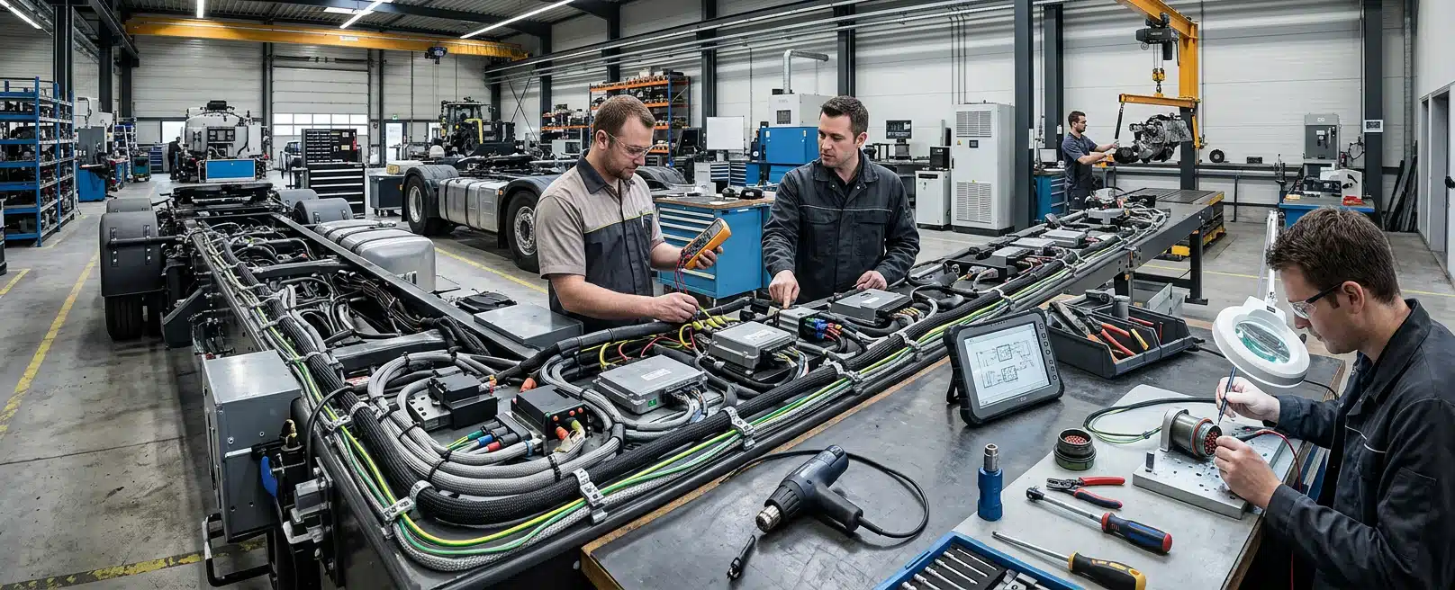
How ISO and SAE Compliance Is Built Into Every Heavy Vehicle Electrical System EI-Group Designs
A heavy vehicle electrical system is judged against the questions the applicable standards actually ask. We do not treat every ISO and SAE document as if it applied to every loom we design. Compliance is a chain from the requirements that belong to this job through to evidence that can be installed and inspected.
ISO publications and SAE recommended practices answer different questions. Mixing them into one generic checklist is how a drawing gets a compliance note without anyone being able to show what was checked on this vehicle variant.
For each heavy vehicle electrical system we design, we apply the ISO and SAE requirements that belong to that job. We then leave records that assembly, inspection and later service can use. Requirements become drawings and checks, not a certificate covering every family.
Which families apply depends on the vehicle, the mounting locations, whether the work is a safety-related electrical and electronic function, and who holds qualified responsibility for the standard. We select and apply them against the actual project. We do not assume a fixed set for mining, agriculture or highway duty.
What Each Family Is Asking
ISO 16750-1 is an environmental document. It applies to electric and electronic systems and components for vehicles, including electric propulsion systems and components with maximum working voltages according to voltage class B. It describes potential environmental stresses and specifies tests and requirements for the specific mounting location on or in the vehicle.
That part also holds the terminology for the ISO 16750 series and the general requirements. It is not intended for motorcycles and mopeds. Electromagnetic compatibility is not covered by this document. If EMC is in scope, it has to be handled under a different document chosen for the job.
ISO 26262-1 is a functional safety vocabulary and framework document. It is intended for safety-related systems that include one or more electrical and/or electronic systems installed in series production road vehicles, excluding mopeds. It does not address unique electrical and electronic systems in special vehicles such as those designed for drivers with disabilities.
It addresses possible hazards caused by malfunctioning behaviour of safety-related electrical and electronic systems, including interaction of those systems. It does not address electric shock, fire, smoke, heat, radiation, toxicity, flammability, reactivity, corrosion or release of energy unless those hazards are directly caused by that malfunctioning behaviour.
SAE J1455 is a recommended practice covering environments that influence the performance and reliability of electronic equipment designed for heavy-duty on- and off-road vehicles. SAE J1939 is a top-level network document. Neither one is a substitute for the other, and neither one replaces ISO environmental testing or ISO functional safety where those families actually apply.
ISO 16750 And Mounting Location
Which Location Sets The Tests
A cabin-mounted module, a chassis-mounted junction and a component on an implement see different environmental loads. The decision is which stresses belong to this connector, controller, harness run or enclosure, given where it sits on the vehicle.
ISO 16750-1 organises the work around that mounting location. Component choice, protection, routing and inspection criteria should follow the location, not a single site-wide rating copied onto every sheet.
Temperature, vibration and ingress limits live in the part and the manufacturer data selected for the job. Our task is to make the location and the requirement visible on the schematic and in the harness documentation so they can be checked.
Edition Matching And EMC Separation
Systems and components already released for production, or already under development before the 2023 edition, can be exempted from fulfilling the changes in that edition compared with the previous one. That matters on a fleet mix of old and new variants. The edition on the drawing has to match the item being designed or altered.
Because EMC is outside ISO 16750-1, a note that environmental tests were considered does not prove electromagnetic performance. If the architecture includes high-voltage propulsion, class B working voltages or dense control electronics, environmental evidence and EMC evidence stay separate.
ISO 26262 And Malfunctioning Behaviour
Whether The Function Falls In Scope
Malfunctioning behaviour of a safety-related electrical or electronic function can create a hazard even when the hardware looks intact. ISO 26262-1 is the vocabulary and framework for handling that class of risk in development. It is not a rule that every mine electrical system, lighting kit or aftermarket fit-out is an ISO 26262 product.
The document describes a framework for functional safety to assist development of safety-related electrical and electronic systems. Some requirements have a technical focus in the product. Others address the development process so an organisation can show capability with respect to functional safety.
Other dedicated application-specific safety standards exist and can complement the ISO 26262 series, or vice versa. Special vehicles and non-series equipment often need that complementary reading. Automotive Safety Integrity Levels, redundancy architecture and any ASIL assigned to a function come from the safety work on that project, not from a default mine classification.
Alterations Versus Clean-Sheet Development
Where the work is an alteration to an existing system, the document addresses tailoring of the safety lifecycle depending on the alteration. Integration of existing systems not developed to this document with systems that were is also handled by tailoring. That is why an upgrade on a vehicle already in service is not treated as a clean-sheet series program.
Hazards from energy, heat or fire that are not caused by malfunctioning electrical or electronic behaviour sit outside this particular scope. Emergency-stop and interlock design still has to meet the functional safety standard stated for the machine. That standard has to be written on the job, not implied by the presence of a safety circuit.
SAE J1455 And Heavy-Duty Electronic Environments
What J1455 Does Not Specify
The same recommended practice also covers appropriate stationary applications that use those vehicle-derived components. Examples in the published scope include on- and off-highway trucks, trailers, buses, construction equipment, and agricultural equipment including implements. A haul truck controller, a trailer module and an implement electronic package can therefore share an environmental conversation even when the chassis and duty differ.
This family is not a cable construction or conductor-sizing code. Using it as a wiring-gauge rule confuses environmental practice for electronic equipment with harness manufacture detail. Conductor size, insulation type and termination method still have to be specified, but they come from the design and the materials chosen for that circuit, not from a misreading of J1455.
We use it when the project actually calls for heavy-duty electronic environmental practice. The record then shows how that practice affected mounting, protection and equipment selection on this vehicle variant.
SAE J1939 And The Network Document Set
Which Documents The Controllers Share
SAE J1939’s top-level document provides a general overview of the SAE J1939 network and describes the subordinate document structure. It includes definitions of terms and abbreviations used among the various subordinate documents.
Added nodes, diagnostic tools or control interfaces need to be designed against the same network family the vehicle already uses. The top-level document tells you where the rest of the set lives. It does not, on its own, specify every cable, terminator or message.
We treat J1939 as a document structure to follow, not as a single page copied onto a schematic title block. If the vehicle does not use this network family, naming J1939 on the drawing does not create compatibility. The first check is which communications documents the existing controllers and the new equipment actually share.
Power and communication architecture still has to be designed so added circuitry does not harm the circuits that keep normal machine operations alive. That check belongs in the design, before a new node is landed on the bus.
From Applicable Requirement To Design Evidence
Once the applicable families are named, they have to become design decisions. A standards list in a proposal is not yet evidence. Evidence is a schematic, harness documentation and an integration model that a workshop or field crew can build and an inspector can follow. That conversion is the work we issue as Engineered Installations Group.
Our electrical engineering work is the place that conversion happens for looms and machinery systems. Electrical schematics are engineering-grade layouts for complete machinery systems and custom wiring harnesses. They exist to remove ambiguity during assembly and troubleshooting, not to decorate a compliance folder.
Harness design documentation includes cut lists, a bill of materials and exact termination instructions. Those sheets are how a connector, a seal, a wire run and a mounting point stay tied to the requirement that justified them. Manufacture and installation can then follow the same joints that were checked against the environmental or safety requirement.
Drafting follows best-practice standards so the same sheet can be used in the bay and later in fault finding. If a termination instruction is missing, the installer is forced to invent a joint. Inspection then cannot tell whether the finished loom still matches the requirement that was designed.
Component and material choices should be traceable to the location and the function. A cabin device and a chassis device should not share a default enclosure note simply because they sit on the same vehicle variant. Where manufacturer environmental data is the evidence, that data stays with the item in the bill of materials.
Integration, Safety Circuits And Commissioning Interfaces
Mounting That Survives The Same Loads
Electrical compliance fails when the loom is treated as a separate product from the structure it is clipped to. Shock, vibration and poor mounting will undo a tidy schematic. Our integrated design service is how mechanical and electrical decisions are brought onto one implementation-ready set of drawings.
Mechanical and structural integration covers robust mounting and protection of electrical and control systems within the vehicle or machine structure, accounting for shock and vibration. If a battery enclosure or frame change is part of the electrical architecture, finite element analysis is how we check the mount against the same dynamic loads the harness was routed to avoid. Where a sensitive controller needs measured machine behaviour rather than a copied location class, vibration data analysis informs the mounting and dampening decision.
Power and communication architecture is designed as a complete network. Added loads, interfaces and control hardware must not starve or disturb the circuitry that already runs the machine. That is a design requirement, not a commissioning surprise.
Safety systems in that scope include compliant, redundant safety circuits such as emergency stops and interlocks, designed to meet the functional safety standards stated for the machine. Redundancy here is a circuit architecture we design when the requirement calls for it. It is not a promise that ISO 26262 has been applied to every mining asset.
The design process runs from feasibility through detailed design to documentation and prototyping support. Feasibility defines system requirements, establishes key performance indicators and includes initial risk assessments. 3D scanning of the existing structure is how we capture the geometry harness routes have to clear. Detailed design produces 3D routing for harness and fluid lines, schematics and mechanical assembly drawings.
Those drawings are then tied to the relevant regulatory standards so manufacturing, installation and certification parties have something concrete to work from. Prototyping and commissioning support sits with your fabrication team to resolve integration issues and support final system testing on that job.
Installation And Verification Evidence
Workshop Fit Versus Field Fit
A compliant drawing can still be installed so that the vehicle no longer matches the design. Routing across a heat source, a missing support, a mis-mated connector or a safety circuit landed on the wrong interlock undoes the design intent. Installation is part of the evidence chain, not an afterthought.
We complete workshop installation at Forrestdale in Western Australia when the vehicle can come to us. When the work cannot be completed there, on-site installation is how we mobilise field technicians, including from Paget in Queensland. Engagements range from a single-unit fit-out to multi-site programs.
Where a light support ute shares the program, braking and suspension upgrades on Australian utes change payload and ride height. The harness still has to land on the tray and chassis points that exist after that work, not on the geometry the old loom assumed.
The method is the same in principle: fit what was designed, then check that it operates as designed. Quality checks before and after install confirm that the work matches the drawings and that the system operates as intended. On a new fit-out, those checks also confirm surrounding equipment was not damaged. On an alteration, the check is against the revised design, including the parts that were meant to change.
Site isolation, lockout and personal protective equipment protect people and the machine during the work. Verification follows the project test plan written for that vehicle. Continuity, function and interface checks belong there, along with as-built notes when the installed route differs from the first issue of the drawing.
Verification should repeat the questions the standards asked. Confirm the device is in the intended location, with the intended protection and terminations. Confirm a network interface matches the communications documents chosen for the job. Confirm a safety stop or interlock behaves as designed, including the failed or isolated condition the drawing required.
Keeping The Evidence Valid In Service
When A Change Reopens The Families
Compliance is not finished at handover. Vibration, heat, moisture, repairs and add-on equipment change the electrical system after it leaves the bay. A later lighting loom, telemetry node or battery management change can quietly leave the original evidence behind.
Vehicle system condition and performance audits, scheduled maintenance servicing and installation aftercare are how we keep that drift visible. Inspection should look for the failures the original requirements were trying to prevent: damaged sheathing, loose connectors, failed seals, unsupported runs and safety circuits that no longer match the drawing.
When a change is more than like-for-like service, treat it as an alteration. Re-open the families that applied. Check whether the mounting location changed, whether a new node landed on the vehicle network, and whether a safety-related electrical function was affected. Then update the schematic and harness records before the next crew has to fault-find from memory.
That is also where older editions matter. A system developed against an earlier issue of ISO 16750-1 or ISO 26262-1 is not automatically out of date because a later edition exists. A current alteration should state which edition it follows, and should not be drawn as if a later edition had been used when it had not.
The Practical Answer
We build applicable ISO and SAE requirements into each heavy vehicle electrical system we design by converting them into schematics, harness documentation and mechanical integration, then installing and checking against those drawings. The four families answer different questions. There is not a single stamp on every loom.
For the next conversation, bring the vehicle variant, the functions being added or altered, the intended mounting locations, any standards already stated by the OEM or site, and the current schematic or harness issue if it exists. With that, we can discuss your requirements against the design, installation and verification evidence this job actually needs.



Leave A Comment