
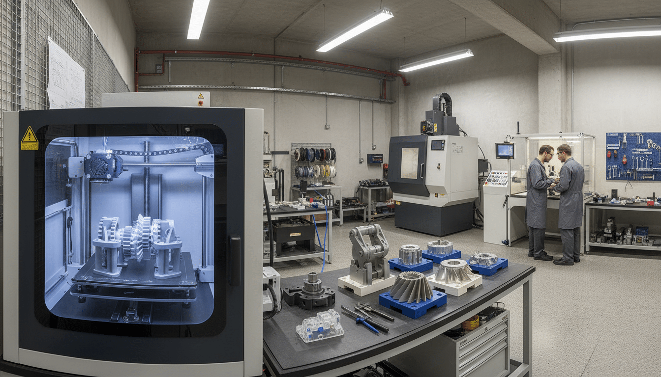
Design validation in mining and heavy industrial sectors traditionally involved lengthy lead times, expensive tooling, and limited iteration opportunities. A single prototype bracket could require weeks of machining time and substantial setup costs. If the design needed modification after testing, the entire process reset. This approach created bottlenecks that delayed projects and increased risk.
Additive manufacturing prototypes have fundamentally changed this equation. Engineers can print a check part and change it before production tooling. The live 3D page lists printing and prototyping. It does not publish a days-versus-weeks guarantee. For industries where equipment operates in harsh environments and safety standards are non-negotiable, this capability represents a significant advancement in how design validation occurs.
How Additive Manufacturing Transforms Industrial Design Validation
Why Traditional Prototyping Created Bottlenecks
Traditional prototyping methods for industrial equipment relied on subtractive manufacturing processes. A machinist would start with a solid block of material and remove everything that was not the final part. This approach worked well for simple geometries but became prohibitively expensive and time-consuming for complex designs. Lead times of four to six weeks were common for a single prototype iteration.
The cost structure created additional constraints. Because each prototype required dedicated setup time and material waste, engineers typically produced only one or two iterations before moving to production. Projects often proceeded with designs that were adequate rather than optimised, simply because another iteration was not feasible within budget and timeline constraints.
What Additive Manufacturing Changes
Additive manufacturing prototypes remove some of these barriers. The process builds components layer by layer from digital files, requiring no dedicated tooling or extensive setup. A design engineer can send a CAD file to a 3D printer in the morning and have a physical prototype by afternoon. Material waste drops dramatically because the printer only deposits material where the design requires it. Customized kits still need that first printed check.
This speed enables true iterative design testing. When EIG validates a new mounting bracket for autonomous mining equipment, the team can produce multiple design variations in the same timeframe that traditional methods would require for a single prototype. Each iteration incorporates lessons from the previous version, resulting in solutions that have been tested and refined through actual use rather than theoretical analysis alone. The cost reduction compared to machined prototypes changes the risk calculation entirely – engineers can afford to test aggressive design concepts and explore multiple approaches without consuming the entire prototyping budget on the first attempt.
Complex Geometries That Traditional Manufacturing Cannot Achieve
Mining and industrial equipment often operates in constrained spaces where every millimetre matters. A sensor housing might need to fit between existing structural members, provide adequate ventilation, protect sensitive electronics from contamination, and mount securely to surfaces that vibrate constantly. Traditional manufacturing methods struggle with these competing requirements because they are limited to geometries that cutting tools can reach.
Internal Channels, Lattice Structures, and Consolidated Parts
3D printing removes some of these geometric constraints. Engineered Installations Group keeps the printed check with the same design pack. Internal channels for cooling or cable routing can follow optimal paths rather than paths that a drill bit can access. Lattice structures can reduce weight while maintaining strength in critical load paths. Multiple components that would traditionally require assembly can be consolidated into a single printed part, eliminating potential failure points from fasteners or joints.
The ability to create complex internal geometries also enables better integration with custom wiring harness design. Electrical engineering solutions benefit directly from this capability – cable routing channels can be designed into structural components, protecting wiring from abrasion and environmental exposure without requiring separate conduit or loom. Connector housings can incorporate strain relief features that would be impossible to machine, reducing the risk of connection failures in high-vibration mining environments.
Better Integration With Mine-Spec Requirements
These geometric capabilities become particularly valuable when validating mine-spec vehicle fitout concepts, including custom wiring harness design – where cable routing channels built into printed brackets can be evaluated for accessibility and protection before committing to production harness fabrication. Engineers can test whether a consolidated multi-function housing actually provides the anticipated benefits, or whether theoretical weight savings translate to practical advantages during installation and operation. Physical prototypes reveal issues that do not appear in CAD models – how difficult it is to route cables through a particular channel configuration, or whether a lattice structure accumulates debris in dusty environments.
The Iterative Design Process With Rapid Prototyping
Effective design validation requires more than confirming that a component matches its CAD model. The part must function correctly when integrated with surrounding systems, withstand the actual operating environment, and remain serviceable throughout its intended lifespan.
From Concept to Workshop Validation
The typical iterative design testing workflow begins with a design concept developed through system design. Customized kits still need that first printed check. 3D services cover the print. Finite element analysis can sit beside a load check. Electrical engineering solutions sit in the same pack when a harness route is being printed around. On-site field services can do a later site check. Engineered Installations Group keeps those notes with the same file. Engineers create the initial CAD model based on known requirements, spatial constraints, and interface specifications. Rather than proceeding directly to production tooling, the team produces an additive manufacturing prototype for form-fit-function testing.
This first prototype reveals practical issues not apparent in the digital model. Perhaps the mounting holes align correctly, but the fastener heads interfere with an adjacent component. Maybe the cable entry point is accessible during initial installation but becomes blocked once other systems are in place. These insights drive the next design iteration. Workshop-based testing allows a controlled check at the Forrestdale workshop. Workshop installation services give a place for that first fit.
Field Testing and Mine-Spec Validation
After workshop validation confirms the basic design approach, field testing begins. On-site field services can do that later site check. Customized kits still need the first printed check. 3D services cover the print. Finite element analysis can sit beside a load check. Electrical engineering solutions sit in the pack when a harness route is printed around. Engineered Installations Group keeps those notes with the same file. Heavy equipment prototyping under actual operating conditions reveals failure modes and environmental interactions that workshop testing cannot replicate. A prototype sensor housing might perform perfectly in the workshop but accumulate dust blocking ventilation in the field. Temperature cycling between day and night shifts might reveal thermal expansion issues. Vibration exposure could identify areas where additional reinforcement is needed.
Each testing phase generates specific feedback driving the next iteration. That loop is useful. It does not prove the final part. Because additive manufacturing prototypes can be produced quickly and affordably, this iterative cycle continues until the design meets all requirements. Only then does the project proceed to production tooling, only after the named checks for that job are done.
Material Selection and Performance Validation
Additive manufacturing prototypes serve multiple purposes throughout design validation, and material selection must align with specific testing objectives. Engineered Installations Group keeps those notes with the same file.
Engineering Thermoplastics for Iterative Testing
Early-stage prototypes focused on form and fit verification can use basic materials that print quickly and cost less. Later-stage prototypes intended for functional testing require engineering-grade materials that approximate production component properties. ABS offers good impact resistance and dimensional stability for housings and brackets not experiencing extreme temperatures. Nylon provides better wear resistance and fatigue properties for components with moving parts or sliding interfaces. Polycarbonate handles higher temperatures and offers superior toughness for parts near heat sources or subject to impact.
A nylon prototype bracket can be used for a vibration check. Vibration data analysis can sit beside that test. If a crack shows, the design can be changed and another print made.
Metal Additive Manufacturing for Final Validation
When applications involve high structural loads or extreme environmental conditions, metal additive manufacturing becomes necessary. Aluminium alloys provide good strength-to-weight ratios suitable for vehicle-mounted equipment. Stainless steel offers corrosion resistance for components exposed to weather or chemical contamination.
Metal printed components can be used for a harder load check. That is a check part, not a production certificate. 3D services cover the print. Customized kits still need that first printed check. Finite element analysis can sit beside a load check. Engineers can conduct destructive testing to verify load capacity and perform fatigue cycling to assess lifespan. The relationship between prototype and production materials requires careful consideration – a nylon prototype may successfully validate geometric design and interface requirements but provide limited insight into how a production aluminium component will respond to thermal cycling.
Integration With Engineering Analysis and System Design
Physical prototyping and digital analysis complement each other throughout the design validation process.
Physical Testing and Digital Analysis as Complementary Processes
Finite element analysis predicts how components will respond to loads, identifies stress concentrations, and optimises material distribution. Physical prototypes verify these predictions and reveal real-world factors that simulations may not capture.
The iterative workflow begins with digital analysis applying expected loads to the CAD model and examining the resulting stress distribution. An additive manufacturing prototype then validates these predictions. Strain gauges applied to critical areas measure actual stress levels during load testing. If measured values align with simulation predictions, confidence in the analysis increases. Discrepancies indicate that the simulation does not fully represent the real loading conditions, prompting refinement of the analysis model.
Complete System Validation Before Production
Custom system design often involves multiple components that must function together reliably. Producing printed prototypes of all components allows assembly and testing of the complete system before committing to production. This system-level validation reveals interface issues, tolerance stack-up problems, and functional interactions that component-level testing misses. EIG’s workshop installation services provide the controlled environment where this complete system validation can be executed methodically, with engineering support available to interpret results and drive design refinements.
Mining Equipment Validation and Compliance Requirements
Equipment destined for mine sites must meet stringent performance and safety standards. Validation processes must demonstrate compliance with relevant regulations, verify compatibility with existing systems, and confirm durability under harsh operating conditions.
Thorough Testing Enabled by Rapid Prototyping
Mine-spec requirements often specify environmental resistance beyond typical industrial standards. Heavy equipment prototyping using additive manufacturing enables more thorough testing than was previously practical within project budgets. Components must function reliably despite exposure to dust, moisture, temperature extremes, vibration, and potential impact. Rapid prototyping enables more thorough validation testing – engineers can produce multiple prototype articles for parallel testing under different conditions. One prototype might undergo accelerated vibration testing while another experiences thermal cycling and a third is exposed to dust contamination. This parallel approach compresses the validation timeline while providing more comprehensive performance data.
Mounting systems for autonomous mining equipment and collision avoidance sensors require particularly rigorous validation. Additive manufacturing prototypes allow testing of various failure scenarios – engineers can deliberately induce overload conditions, examine how the component fails, and verify that the failure mode does not create additional hazards. Engineered Installations Group applies this validation approach across mine-spec vehicle fitout programs and heavy equipment modification projects, ensuring that designs are proven before production quantities are committed.
Documentation and Traceability
Documentation and traceability requirements for mining equipment validation benefit from rapid prototyping workflows. Each prototype iteration can be tested systematically with results documented in detail. This testing history demonstrates due diligence in the design process and provides evidence that the final design has been thoroughly validated. For projects requiring formal design verification, this documentation supports compliance with quality management systems.
Contact us to check the current prototype scope.



Leave A Comment