
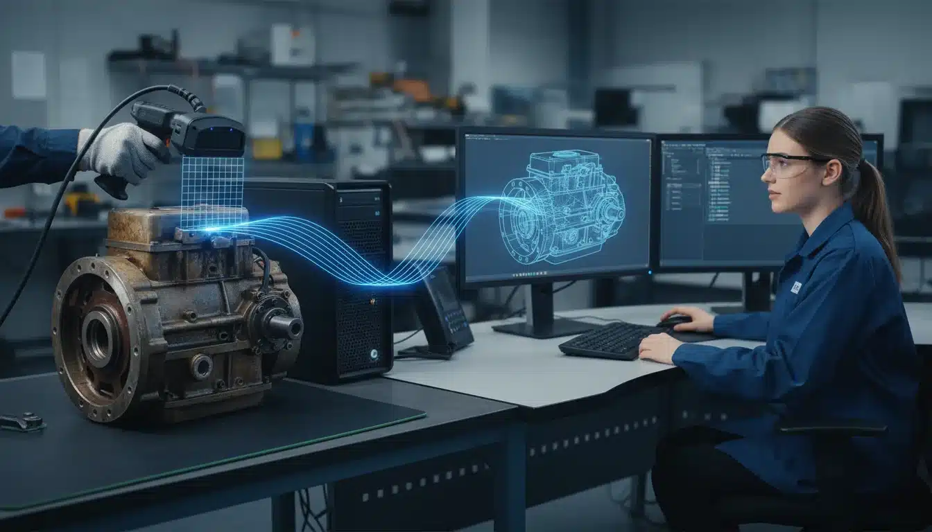
When original equipment drawings are missing, components need retrofitting, or legacy systems require modification, having accurate digital models becomes essential. Scan-to-CAD conversion provides that foundation, transforming physical equipment into precise 3D models that engineering teams can actually use for design, analysis, and fabrication work.
Reverse engineering services bridge the gap between what exists in the field and what the drawing pack needs. Rather than relying on manual measurements or outdated documentation, 3D laser scanning captures complex geometry as a dense point set that get converted into clean, parametric CAD models compatible with standard engineering software.
This process proves particularly valuable in mining and heavy industrial contexts where equipment modifications are frequent, original manufacturers may no longer exist, and downtime costs make trial-and-error approaches financially unviable. A properly executed scan-to-CAD workflow delivers dimensional certainty before fabrication begins.
What Scan-to-CAD Conversion Actually Delivers
Reverse engineering services start with physical objects and produce digital models – but the value lies in what those models enable.
From Physical Objects to Usable Engineering Models
A completed scan-to-CAD project delivers a CAD file the drawing pack can use. The live 3D page lists scan conversion. It does not name a CAD brand or a millimetre target. System design holds the mechanical and electrical interfaces in one model.
The foundation comes from 3D laser scanning technology that captures millions of measurement points across equipment surfaces. Modern laser scanners achieve accuracy within ±0.5 mm across typical industrial scanning distances, creating datasets that represent physical geometry in three-dimensional space. This density of measurement data exceeds what manual methods can practically achieve, particularly for complex curved surfaces or assemblies with restricted access.
Interpreting Design Intent, Not Just Generating Surfaces
Converting point cloud data into usable CAD models requires more than automated surface generation. The process involves interpreting design intent – identifying which features are cylinders, planes, or specific geometric relationships – and reconstructing that geometry using parametric modelling techniques. The result is digital twin creation that behaves like originally designed parts, with dimensions that can be modified and features that maintain proper geometric relationships.
For mining operations and heavy vehicle applications, this means retrofit projects can proceed with confidence in dimensional compatibility. Custom brackets, mounting plates, or interface components can be designed against accurate digital representations of existing equipment, eliminating the multiple iterations that often result from working with approximate measurements or outdated drawings. EIG’s 3D services deliver this complete workflow – from field scanning through point cloud processing to final parametric CAD model delivery.
The Four-Phase Scan-to-CAD Workflow
EIG’s scan-to-CAD workflow prioritises accuracy, efficiency, and usability of final deliverables.
Phase 1: Site Assessment and Scan Planning
Effective reverse engineering services begin before scanning equipment arrives on site. On-site field services can do the capture. Finite element analysis can sit beside the model when a mount is being checked. The assessment phase identifies what needs capturing, determines access requirements, and establishes accuracy targets that align with how the models will be used. A component destined for clearance checking requires different scan density than one being replicated for fabrication.
Site conditions influence scanning strategy significantly. Equipment mounted in confined spaces, components with highly reflective surfaces, or assemblies that cannot be moved require specific scanning approaches and sometimes supplementary measurement techniques. Understanding these constraints upfront prevents data gaps requiring return visits – particularly important for remote mine sites where return visits carry significant cost and schedule implications.
Scan planning also addresses coordinate system requirements. Models need proper orientation and datum references that align with existing engineering documentation or site coordinate systems. Establishing these references during initial setup ensures final CAD models integrate seamlessly with other project data.
Phase 2: 3D Laser Scanning and Data Capture
The scanning phase captures physical geometry as scan data using laser-based measurement systems. Engineered Installations Group keeps that scan with the same design pack. Scanners project laser lines or patterns onto equipment surfaces, measuring millions of points per second to build a three-dimensional representation of everything within the scanning volume.
Multiple scan positions are typically required to capture complete geometry, particularly for complex assemblies or equipment with obstructed areas. Each scan position captures geometry from a different perspective, and these individual scans get aligned into a unified dataset using common reference features or targets placed in overlapping scan areas.
Quality verification occurs during data capture, not after. Checking point cloud density, identifying areas requiring additional scanning, and confirming adequate overlap between scan positions prevents discovering gaps during later modelling phases.
Phase 3: Point Cloud Processing and CAD Modelling
Raw scan data requires substantial processing before CAD modelling begins. Point clouds are cleaned to remove noise, extraneous data, and artefacts from the scanning process. Individual scans are precisely aligned using registration algorithms that identify common features and minimise alignment errors across the complete dataset.
The registered point cloud becomes the reference for CAD model creation. Rather than simply generating surface meshes from point data, proper reverse engineering involves interpreting geometric features and reconstructing them using parametric CAD techniques. Cylindrical features are modelled as true cylinders with defined diameters and axes. Planar surfaces are reconstructed as planes with specific orientations. Geometric relationships like perpendicularity, concentricity, or symmetry are identified and incorporated into the CAD model structure.
This parametric approach produces models that behave correctly when modified. Vibration data analysis can sit beside a mount check. System design holds the mechanical and electrical interfaces in one model. A hole diameter can be changed without distorting surrounding geometry. Mounting bracket positions can be adjusted while maintaining proper alignment relationships.
Phase 4: Quality Assurance and Model Delivery
Completed CAD models undergo deviation analysis comparing model geometry against original point cloud data. This comparison generates colour-mapped reports showing where the CAD model deviates from scanned geometry and by how much. Deviation limits belong in the job spec, not as a published EIG figure. Typical industrial projects may set their own limit for general geometry and under 0.5 mm for critical interface features.
Areas showing excessive deviation are investigated and corrected. Sometimes these represent modelling errors requiring geometry adjustment. Other times they indicate damaged or deformed areas on the physical equipment that should not be replicated in the CAD model. Understanding which situation applies requires engineering judgement informed by how the model will be used.
Final deliverables include native CAD files in client-specified formats, deviation analysis reports documenting model accuracy, and often the registered point cloud data itself. Providing point cloud data alongside CAD models allows engineering teams to reference original scan data when questions arise during subsequent design work.
Common Applications in Mining and Heavy Industry
Reverse engineering services address practical problems that arise frequently in mining operations and heavy industrial environments.
Equipment Retrofit Projects and Obsolete Part Replication
Equipment modification projects represent the most common application – fitting new monitoring systems, adding safety equipment, or integrating upgraded components into existing vehicles or machinery. Having accurate CAD models of existing equipment allows new components to be designed with confidence in dimensional compatibility.
Obsolete part replication provides another frequent use case. When components fail on equipment no longer manufactured and original drawings are unavailable, scan-to-CAD conversion enables creating accurate replacement parts. The scanned component gets converted to a CAD model suitable for manufacturing through machining, fabrication, or additive manufacturing processes.
Custom integration projects benefit significantly from accurate as-built models. Installing collision avoidance systems, integrating autonomous vehicle components, or fitting specialised equipment packages all require precise knowledge of existing vehicle or equipment geometry. EIG’s electrical engineering solutions particularly benefit from accurate 3D models that show actual cable routing paths, mounting locations, and clearance constraints – enabling digital harness routing that eliminates trial-and-error during installation.
Clash Detection and Fleet Documentation
Digital twin creation enables critical clash detection and clearance verification during modification design phases. Before committing to fabrication, engineering teams can verify that new components fit within available space, do not interfere with existing systems, and maintain required clearances for operation and maintenance. Discovering these issues digitally costs significantly less than discovering them during installation.
Documentation of as-built conditions provides value beyond immediate project needs. Mining operations maintaining fleets of modified equipment benefit from having accurate digital records of what actually exists on each vehicle. This documentation supports maintenance planning, spare parts management, and future modification projects. When workshop installation services need to replicate a successful modification across multiple vehicles, having accurate CAD models of the original installation eliminates guesswork and ensures consistency across the fleet.
Why Accuracy Matters in Industrial Reverse Engineering
Dimensional accuracy in scan-to-CAD conversion is not about achieving arbitrary precision – it is about ensuring models support their intended engineering applications without introducing errors that compromise downstream work.
Tolerance Requirements and Error Propagation
Functional mechanical components require the tightest tolerances. A mounting bracket designed to interface with scanned geometry needs hole positions accurate enough that bolt patterns align without forcing parts. These applications typically require scan-to-CAD accuracy within ±0.5 mm for critical features.
Clearance checking and interference verification accept somewhat looser tolerances. Verifying that a new component fits within available space without contacting existing equipment can often work with ±2 mm accuracy, provided that safety margins account for this measurement uncertainty.
Measurement errors compound in assembly situations. If two mating components each carry ±0.5 mm dimensional uncertainty, the assembled relationship carries ±1 mm potential error. Multi-component assemblies can accumulate significant uncertainty if component measurement errors stack unfavourably. Proper reverse engineering practice minimises these effects through careful datum selection and measurement strategy.
When Physical Conditions Complicate Accuracy
Worn equipment surfaces, corroded areas, or components with damaged geometry present challenges. Scan-to-CAD conversion can document these conditions, but engineering judgement is required to determine whether models should replicate as-found conditions or represent idealised geometry representing original design intent.
For projects involving finite element analysis or other simulation work, model accuracy directly impacts analysis validity. Structural analysis of a scanned component relies on accurate geometry to predict stress distributions and deflections correctly. Using models with inadequate accuracy for these applications produces unreliable analysis results that can lead to incorrect engineering decisions.
How Scan-to-CAD Supports Downstream Engineering
The value of reverse engineering services extends well beyond simply having 3D models of existing equipment.
Structural Analysis and Harness Design
Integration with finite element analysis workflows allows structural verification of existing components or assessment of how modifications affect load paths and stress distributions. A scanned equipment frame can be analysed to determine where reinforcement is needed before adding heavy auxiliary equipment.
Custom wiring harness design relies heavily on accurate 3D models showing actual cable routing paths, mounting points, and clearance constraints. Rather than discovering interference issues during installation, custom wiring harness design can proceed against accurate digital geometry – verifying clearances and optimising routing paths before fabrication begins. This approach reduces installation time and eliminates the trial-and-error that often characterises field harness installations on vehicles without accurate as-built documentation.
Installation Planning, Field Service, and Configuration Management
Workshop installation planning benefits from having complete digital representations of equipment before it arrives at the facility. Installation teams can pre-fabricate mounting brackets, prepare cable assemblies, and stage components knowing they will fit correctly. This preparation reduces vehicle downtime and improves installation efficiency.
Field service preparation uses scanned models to understand equipment configuration before technicians deploy to remote sites. Understanding what actually exists on a vehicle, where components are mounted, and what access constraints apply allows better planning of required tools, parts, and procedures – particularly valuable for remote mine sites where returning for incorrect parts carries significant time and cost penalties.
Documentation and configuration management represent longer-term benefits. Engineered Installations Group keeps those records with the same pack. Customized kits still need the scanned shape before later kits are copied. Vibration data analysis can sit beside a mount check. System design holds the mechanical and electrical interfaces in one model.
As equipment gets modified over its service life, maintaining accurate digital records of current configuration supports maintenance planning, spare parts management, and future modification work. Mining operations managing fleets of customised vehicles benefit from having authoritative digital records rather than relying on incomplete paper records.
Engineered Installations Group maintains this integrated approach – connecting scan-to-CAD conversion directly to system design, electrical engineering, and installation services to provide a complete pathway from measurement through to installed, commissioned equipment.
For organisations dealing with equipment modifications, obsolete part replacement, or custom integration projects, Contact us to check how a scan-to-CAD file can support the current job.



Leave A Comment