
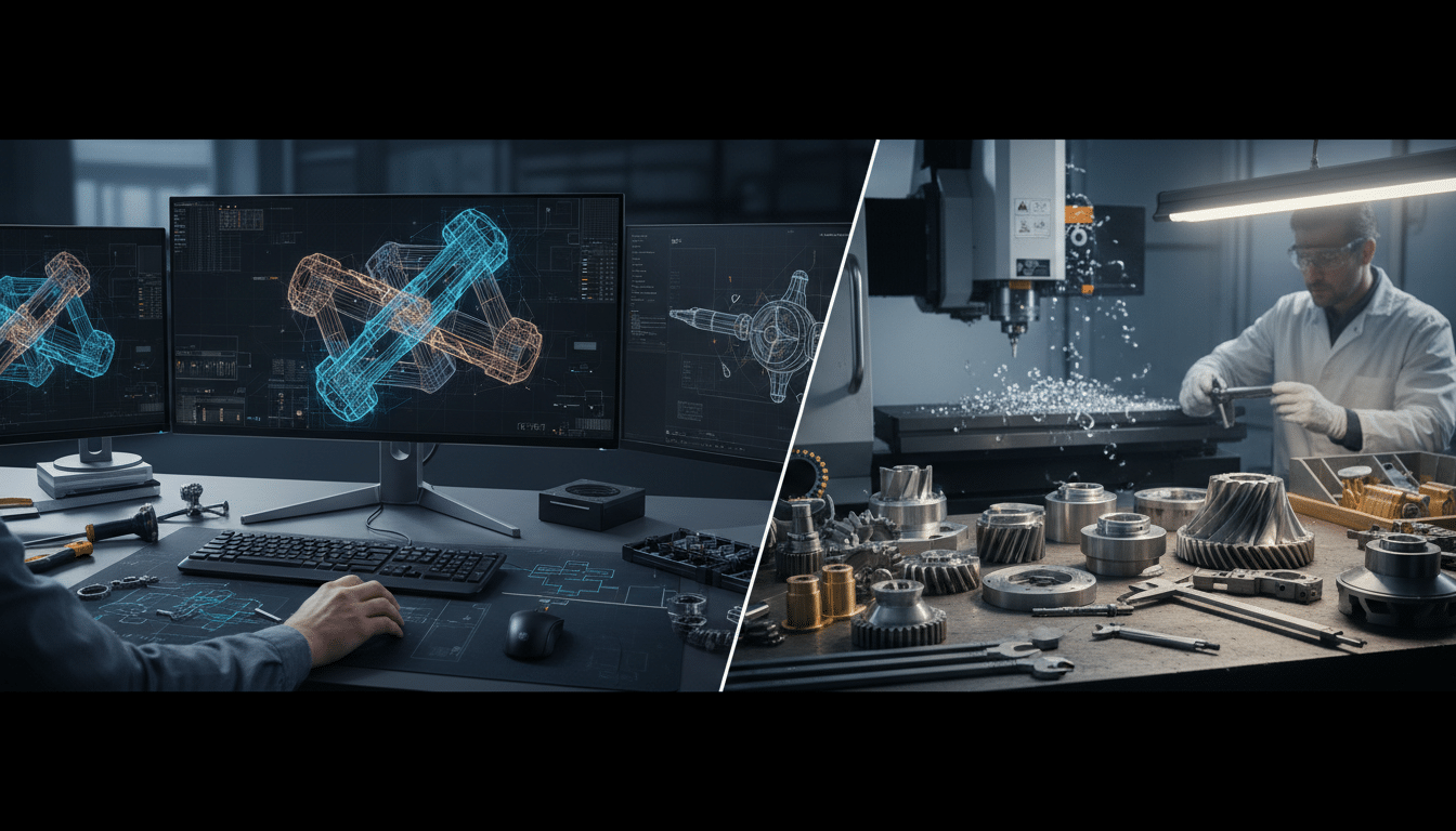
Turning an engineering concept into a physical component requires more than sketching ideas on paper. It demands precise digital modelling, careful consideration of manufacturing constraints, and rigorous validation before a single part reaches production. For mining and heavy industrial operations, where component failure can halt entire sites and create substantial downtime costs, the quality of 3D component design directly impacts operational reliability.
CAD geometry optimisation sits at the heart of this transformation. It is the process of refining digital models so dimensions, tolerances and features can be made and fitted. When executed properly, it eliminates the costly cycle of design-manufacture-fail-redesign that plagues projects lacking thorough upfront engineering.
The Foundation of Modern Component Design
3D CAD modelling services have evolved far beyond simple digital drafting. Modern parametric CAD systems enable engineers to create intelligent models where dimensions and features relate to each other through defined parameters and constraints.
From Digital Drafting to Intelligent Parametric Models
Change one dimension, and related features update automatically throughout the model. Finite element analysis can sit beside that model when a mount is being checked. This capability proves essential when designing components that must integrate with existing equipment or accommodate site-specific modifications.
The mining sector presents particularly demanding design challenges. Components must withstand extreme vibration, abrasive dust, temperature fluctuations, and constant mechanical stress. A mounting bracket that works perfectly in a climate-controlled workshop might crack within weeks at a remote mine site. Effective CAD geometry optimisation accounts for these operational realities from the first sketch. Vibration data analysis can sit beside a mount check.
What CAD Geometry Optimisation Involves
Consider a custom mounting system for autonomous mining sensors. The initial concept might show a simple bracket attaching to a vehicle frame. Through proper 3D component design, engineers refine this concept by analysing load paths, identifying stress concentrations, optimising wall thicknesses, and ensuring the geometry can actually be manufactured with available processes. The digital model becomes a complete specification that machinists, fabricators, or 3D printing operators can execute without ambiguity.
EIG’s system design process applies CAD geometry optimisation as a standard element of custom component development – not as an optional refinement applied after the design is functionally complete, but as an integral part of the design process from the outset.
Design for Manufacturability: Engineering With Production in Mind
Design for manufacturability represents a fundamental shift in engineering approach. Rather than designing an ideal component and then figuring out how to make it, engineers consider manufacturing constraints throughout the design process. This methodology reduces production costs, shortens lead times, and improves component quality.
Common Manufacturability Issues and How to Address Them
Common manufacturability issues include inaccessible features requiring special tooling, unnecessarily tight tolerances that increase machining cost without improving function, undercuts preventing mould release, thin walls causing warping, and sharp internal corners creating stress concentrations. Addressing these issues during the CAD geometry optimisation phase prevents expensive surprises during production. An experienced design engineer reviews each feature asking: can this be manufactured efficiently? Does this tolerance actually matter? Is there a simpler geometry that achieves the same function?
Designing for Field Repairability in Mining
For mining applications, design for manufacturability extends beyond the initial production run. Components often require field repairs or modifications at remote sites with limited equipment. A design that can only be manufactured on a specialised five-axis CNC machine becomes a liability when it fails 800 kilometres from the nearest major workshop. Smart design considers repairability and allows for fabrication using more widely available processes – a practical requirement that shapes geometry decisions from early in the design phase.
Parametric Modelling: Building Flexibility Into Design
Parametric modelling techniques enable design flexibility that would be impractical with traditional fixed-geometry CAD. In a parametric model, dimensions are defined as variables rather than fixed values, and relationships between features are captured through constraints and equations.
Creating Reusable Design Frameworks for Fleet Applications
A mine-spec vehicle fitout might require sensor mounting systems for many vehicles across several different makes and models. Rather than creating separate designs from scratch for each vehicle, engineers develop a parametric master model where key dimensions – mounting hole spacing, bracket width, sensor offset – are defined as parameters. Adjusting these parameters generates a new variation optimised for each vehicle configuration, dramatically reducing design time whilst maintaining consistency.
EIG’s 3D modelling services apply parametric modelling techniques as standard practice on fleet fitout programs, where the upfront investment in a well-structured parametric model pays back across every subsequent vehicle variation.
Long-Term Adaptability and Design Optimisation
The benefits extend throughout a component’s lifecycle. Engineered Installations Group keeps that model with the same design pack. Customized kits still need the same platform check. Vibration data analysis can sit beside a mount check. Workshop installation services give a controlled place for the first fit. When a client needs to accommodate a different sensor model two years after initial installation, the parametric model allows engineers to quickly adjust mounting geometry and regenerate manufacturing drawings. Parametric modelling also facilitates design optimisation – programmatically varying parameters and evaluating results through simulation or analysis makes testing dozens of bracket thickness variations a matter of hours rather than weeks.
From Digital Model to Physical Prototype
The prototype development process validates design decisions before committing to full-scale production. For complex or high-value components, prototyping identifies issues that might not be apparent in even the most thorough digital analysis.
Prototyping Methods and Their Applications
Modern prototyping encompasses several approaches. 3D services cover printing and prototyping. On-site field services can do a later site check. 3D printing can produce a check part quickly for fit. Time depends on the part and the printer. The live page lists printing and prototyping. It does not publish a hours-or-days guarantee. CNC machining creates prototypes from actual production materials, providing accurate mechanical testing and validation. Fabrication prototypes use the same processes planned for production – welding, forming, assembly – revealing manufacturing challenges before full production begins.
For a custom wiring harness mounting system, the prototype development process might begin with 3D-printed brackets to verify fit and clearance on the actual vehicle. Workshop installation services give a controlled place for that first fit. Once geometry is confirmed, CNC-machined prototypes undergo vibration testing to validate structural performance. This staged approach catches issues early when changes are inexpensive.
Prototypes as Communication Tools
The prototype development process also serves as a communication tool. Customized kits still need the same platform check. Vibration data analysis can sit beside a mount check. Workshop installation services give a controlled place for the first fit. Showing a physical prototype to maintenance technicians or operators often reveals practical concerns that do not emerge in design reviews. A bracket that looks perfect in CAD might prove difficult to install in the cramped confines of an equipment bay – something immediately obvious when technicians handle the prototype.
Quality Assurance and Design Validation
Quality assurance in 3D component design extends beyond dimensional accuracy. It encompasses functional performance, manufacturability, assembly considerations, and long-term durability.
Multi-Stage Validation Before Production
Design validation typically progresses through multiple stages: geometric verification, interference checking, structural analysis through finite element analysis, vibration analysis evaluating component response to dynamic loads, and tolerance stack-up analysis ensuring accumulated manufacturing variations will not prevent proper assembly.
For components experiencing dynamic loads or harsh environments, coupling 3D CAD modelling services with analytical validation is essential. A mounting bracket might appear robust in static analysis but develop fatigue cracks under vibration. Identifying this during design allows engineers to add reinforcement or modify geometry before manufacturing.
Documentation for Consistent Production
A complete 3D component design package extends beyond the CAD model itself. Engineering drawings communicate dimensional requirements, tolerances, surface finishes, and material specifications. For complex assemblies, exploded views and assembly instructions prevent production and installation errors. Bill of materials documents specify every component, fastener, and purchased part required.
This documentation becomes particularly important for mining projects where components may be manufactured by subcontractors or replicated years after initial production. Clear, complete documentation ensures consistency and enables future reproduction without reverse-engineering.
Industry Applications: Mining and Heavy Industrial Sectors
Mining operations demand components engineered to survive conditions that would destroy standard commercial parts. Dust infiltration, extreme vibration, temperature cycling, chemical exposure, and mechanical impacts are daily occurrences.
Custom Sensor Mounts and Heavy Vehicle Modifications
Custom sensor mounts for autonomous mining systems exemplify these challenges. The mount must position sensors with millimetre precision for proper system function, yet withstand constant vibration that would quickly fatigue a poorly designed bracket. It must seal against dust ingress whilst allowing sensor cooling. It must survive impacts. And it must facilitate maintenance access in the field.
Heavy vehicle modifications present similar challenges. Custom mounting systems for collision avoidance equipment, fleet management hardware, or communication systems must integrate with existing vehicle structure without compromising strength or creating new failure points. Component design for mining applications also addresses repairability – a complex cast component might offer optimal performance but become a liability if damaged at a remote site.
Material Selection as a Design Parameter
Proper material selection forms a critical element of 3D component design. The same geometry manufactured in different materials can exhibit vastly different performance. Aluminium alloys offer excellent strength-to-weight ratios for vehicle-mounted components where weight matters. Steel provides superior stiffness and strength at lower cost. Engineering plastics and composites suit applications where chemical resistance, electrical insulation, or weight reduction are priorities.
Material selection influences the final geometry directly – a bracket designed for steel fabrication requires different geometry than one designed for aluminium machining. Experienced design engineers consider these factors from the first iteration rather than attempting to adapt a completed design to an unsuitable material.
Integration With Broader Engineering Services
3D component design rarely exists in isolation. It typically forms part of a broader engineering solution encompassing electrical integration, structural analysis, prototyping, and manufacturing support.
Collaboration Between Mechanical, Electrical, and Installation Disciplines
For a complete vehicle fitout, electrical engineering solutions work alongside mechanical design to ensure proper cable routing, connector accessibility, and electromagnetic compatibility. Mounting brackets must accommodate wiring harnesses. Panel layouts must provide maintenance access to both mechanical and electrical components.
Mechanical, electrical and install notes should sit in one pack from the start, so a later change does not surprise the floor.und but practically manufacturable and installable in actual field conditions – a distinction that matters enormously when equipment operates 800 kilometres from the nearest engineering support.
For projects requiring precision-engineered components that must perform reliably in harsh industrial environments, Contact us to check the current component design scope with engineers who understand the unique challenges of mining and heavy industrial applications.



Leave A Comment