
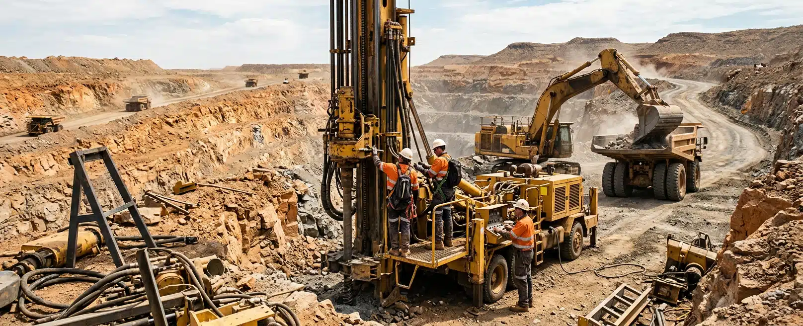
Hard-rock mining equipment is modified for a defined job. That job might be extra lighting, a collision-avoidance kit, a battery enclosure, a control cabinet, a reinforced bracket, or a harness that electricians can fault-find without stripping half the machine.
We design, document and install that change against abrasive rock, vibration and the way your fleet is actually maintained. Purpose-built mining engineering solutions start from the duty of that asset.
Hard rock is a geological condition, not a mine layout. Iron ore, gold, nickel and copper fleets work in open pits and underground. Treating hard-rock duty as a synonym for a heading produces the wrong picture of access, dust, heat and isolation time. Start with the machine, the modification and the environment it will run in.
Hard-Rock Duty And Mine Layout Are Separate Problems
Abrasive rock, drill and blast vibration, haul-road shock and fine angular dust appear on surface and underground fleets. What changes is how those loads reach the equipment and how anyone gets time on it.
A haul truck in a hard-rock pit sees continuous chassis motion, airborne fines and impact from spillage. A jumbo, loader or charge-up vehicle underground sees confined access, different lighting and a different isolation window.
Electrical and mechanical design still has to account for vibration, contamination and service access. Those conditions also govern how the kit is fitted and how it will be reached later.
Name The Rock Duty And The Setting
Geology sets dust, shock and wear on looms, mounts and enclosures. Layout sets whether the unit can travel to Forrestdale or whether we have to mobilise to the asset.
Our work sits on machinery, heavy vehicles and mobile equipment. Mixing geology with layout is how a surface-capable kit is specified as if it will live in a heading. It is also how an underground access constraint is ignored because the rock type sounded similar.
If the modification is a loom, a cabinet, a mast or an integrated safety system, name both the rock duty and the setting. One without the other leaves strain relief, connector choice, mount stiffness and last connections guessing.
Assess The Environment That Machine Actually Sees
Purpose-built here means the design starts from the duty of that asset. Continuous vibration loosens terminals, work-hardens conductors at poorly supported terminations and fatigues brackets that were only ever sized for a static box.
Hard, angular dust abrades looms, packs into connectors and coats surfaces that reject heat. Thermal cycling opens seal gaps and changes contact resistance.
Tell us where the machine works, what it does, and what already fails on that circuit or structure. That assessment decides how much of the job is documentation versus metalwork.
If the existing harness cannot be traced, every later fault takes longer than it should. If a new enclosure or sensor mast is welded or bolted onto a chassis that already flexes, the mount is a structural question, not a catalogue bracket.
If the machine cannot leave site, the same drawings still have to be installable in the isolation window the mine will actually give. That window is the locked-out time available on the asset, plus the laydown space around it.
Vibration As A Design Input
We use vibration data analysis where a repeating mechanical mode is the issue. Typical modes are imbalance, misalignment, bearing or gear mesh, or a mount that feeds vibration into electrical hardware.
On mobile plant that work has to cope with variable speed, variable load and rough terrain. It is a measurement and design input. It does not mean every fault will announce itself months ahead.
Finite Element Work On Geometry
Finite element work belongs when geometry, materials and load cases need to be tested before steel is cut. Both tools serve the modification in front of you. Neither replaces naming the machine.
Schematics And Harnesses That Can Be Serviced
Hard-rock mining equipment is repaired by people who were not in the design meeting. A loom that only exists in one fitter’s head fails that test.
Documentation And Routing
Our electrical engineering for machinery and mobile plant is built around engineering-grade schematics for complete systems and custom wiring harnesses. Harness documentation includes cut lists, a bill of materials and termination instructions. Those deliverables make assembly repeatable and field faults traceable.
Routing is part of the same decision. A harness that takes a sharp bend against a chassis rail will consume shutdown time. So will a loom that crosses an articulation point without allowance for movement, or that hides a breakout where nobody can reach a failed pin.
A serviceable loom on this duty usually needs:
- Strain relief at exits from the main loom
- Abrasion protection where the loom can rub
- Breakouts placed where a failed pin can be reached
- Allowance for movement at articulation points
Fine-strand flexible conductors are the usual construction where vibration would fatigue a stiffer cable. The schematic still has to show what was fitted so the next repair does not substitute the wrong section.
Power Architecture And Safety Circuits
Power architecture has to sit beside the circuits that already run the machine. Adding lighting, telematics, collision-avoidance hardware, a battery enclosure or a control cabinet can starve the original system, or couple electrical noise into it, if distribution is treated as an afterthought.
Our system integration covers power and communication networks with that constraint in view, together with emergency stops and interlocks intended to meet functional safety requirements for the application. You still have to state which systems must remain live, which must isolate, and which OEM functions must not be altered.
Electrified excavators and other high-voltage mobile assets raise the same issues at higher energy: electrical architecture, high-voltage harness routing and the safety circuits around them.
Where a battery enclosure or frame change is part of the modification, we develop the electrical layout and the structure together. Otherwise the enclosure becomes a box the chassis was never asked to carry. That pairing is our work as Engineered Installations Group on the same asset.
Mounts, Frames And Load Assumptions
A camera, radar, cabinet or battery enclosure is only as reliable as what holds it. On hard-rock plant the mount sees shock from the road or heading, vibration from the driveline and drills, and handling loads when the unit is jacked, lifted or transported.
What The Model Can Estimate
We use structural analysis to quantify stress, deflection, vibration and thermal behaviour. We also look at fatigue, buckling and joint detail on brackets, frames and field modifications.
Typical studies include linear and nonlinear cases, modal and harmonic response, impact, thermal and thermo-mechanical behaviour, and checks on welds, fasteners, lifting and jacking loads.
The model is only as good as the duty and load cases you can state. If the duty is not described, the analysis is guessing.
If the duty is known, the model can estimate whether a proposed mast is at risk of cracking at the weld under those cases. It can also estimate whether a battery enclosure needs a different rib, or whether a retrofit bracket overloads a chassis rail.
Correlation with tests and documented assumptions belong in the design records when the modification has to be defended later. FEA can also supply traceable evidence against requirements such as ROPS/FOPS or structural integrity where those are the actual question. That evidence supports a safety case. The site still runs its own certification path.
Root-cause work is the other use of the same tool. When a mount or frame has already cracked, simulating the loads that led there can support a design change. That simulation does not, by itself, stop the same crack appearing across the fleet.
That only helps if the failed geometry, material and operating history are available. Bring the cracked part, the machine identity and the hours or duty cycle, not a request for a generic stronger bracket.
Scanning The As-Built Machine
Three-dimensional scanning and modelling help when the as-built machine does not match the drawing, or when a guard hides the face that has to take a mount. As-built here means the machine as it actually is, including previous modifications. Scan data feeds harness routing and mechanical assembly drawings.
We use 3D scanning to capture that geometry before the mount or loom is committed. Printing and prototyping are useful where a fit check is cheaper than a wrong cut of plate. They support a defined modification by giving the electrical and structural work a measured surface to design against.
Safety And Control Gear As Integration
Australian hard-rock fleets often add extra systems to machines that already have a dense electrical and hydraulic layout. Typical additions include collision avoidance, mobile terrain awareness, autonomous mining safety systems, fleet management, communications, driver monitoring, lighting, battery management or jump-start gear.
We install those systems and connect them to the existing machine. The engineering question is whether the chosen kit can be mounted, powered, networked and checked without damaging OEM circuits or leaving a loom that cannot be maintained.
Circuits, Isolation And As-Built Records
Mixed traffic on a pit ramp or in a heading makes that work unforgiving. A unit that nuisance-brakes, drops off the network or presents a dark camera needs a measured check, not an assumed cause.
Power quality, mount damping, connector contamination, undocumented harnesses and software configuration can all produce the same symptoms. Mechanical and electrical integration, including shock and vibration protection of electrical hardware, is part of that check.
Vibration data on proposed mounting points tells us whether dampening is needed before the hardware is fitted. Emergency controls and interlocks have to be designed as circuits, not as labels. Safety architecture is a functional-safety choice for the application.
Tell us which stop functions, which isolation points and which OEM interlocks the modification must respect. Checking after install then confirms that the installed system matches that intent. When field changes are required, we update the documentation to the as-built arrangement.
Forrestdale Workshop Or Work That Has To Happen On Site
Some modifications can be built and proven on the machine in a workshop. Others cannot, because the asset will not leave site or because the last connections only exist against mine infrastructure.
Workshop Versus Site
Our workshop installation operates from Forrestdale, Western Australia. Our field services cover installations, commissioning and related support when the work cannot be completed at the Perth facility, from a single-unit fit-out to a longer multi-site program, with the on-site workforce scaled to the schedule.
A practical split looks like this:
- Workshop: harness manufacture, cabinet build, trial routing and bench checks
- Workshop: pre-install and post-install checks before the machine leaves
- Site: machines that stay on the roster
- Site: connections that only exist next to the fleet network
- Site: checking under the mine’s isolation and permit regime
We work with operations on delivery schedules, multi-team coordination and commissioning requirements. Isolation practice includes lock-out/tag-out, PPE and isolations. Those are working controls. The mine’s own rules still govern the job.
Support around a mining modification can include engineering data capture, equipment scans and vibration data capture. It can also include project deployment support, autonomous mining and safety system implementations, breakdown support, shutdown labour and component changeouts where that is the engagement.
After a fit-out, condition and performance audits, scheduled servicing and installation aftercare apply when they are in scope. The modification defines which of those steps are required. They do not all have to travel together.
Where someone has to stand next to the machine, geography decides the contact point. Goldfields and Pilbara work that can travel still points at Forrestdale.
Work that cannot travel, including Bowen Basin plant, is a site mobilisation, with Queensland contact at 13 Ginger Street, Paget. Western Australia remains Unit 2, 17 Bessemer Road, Forrestdale.
Neither address changes the engineering sequence. We move from requirements and risk, through detailed design and modelling including three-dimensional routing of harness and fluid lines, then documentation for manufacture and installation. After that we work with the fabrication and install teams through commissioning.
Light Support Utes Under Extra Load
The plant modification is one job. Australian light support utes on the same site can be another, if extra tray, canopy or toolbox load has changed how they sit and stop.
For those utes, braking and suspension upgrades manage increased GVM and stopping under that changed load. That is a payload and handling decision on the ute, not a substitute for the plant electrical or structural work.
The Fit For This Modification
Bring a named machine and a named change. From that we can say whether the electrical, structural and install work belongs with us, and whether it happens in Forrestdale or on site.
The practical test is whether you can describe the asset and the change. Photographs of install faces, connector locations and damaged mounts help when drawings are stale. Site access rules, isolation windows and which OEM functions must remain untouched decide the install method.
Send us:
- Machine make, model and identity
- The duty, including what it does and in which pit, stope or road
- The modification: what is being added, moved or reinforced
- Existing electrical and structural drawings if they exist
- Known failure history on that circuit or structure
- Whether the unit can come to Forrestdale or must stay on site
Those inputs are enough to discuss the project as a scoped technical conversation.



Leave A Comment