
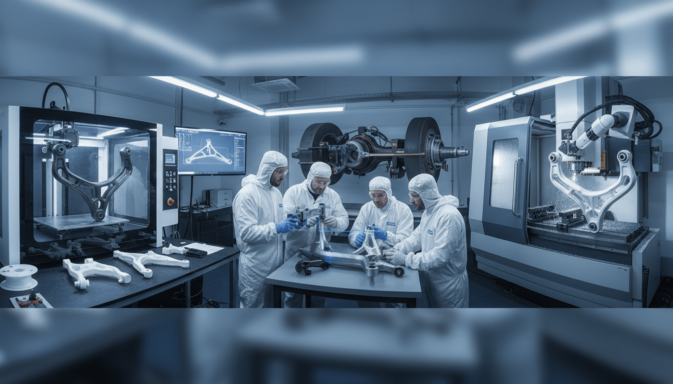
Custom component development for automotive and heavy equipment applications traditionally involves lengthy prototyping cycles, multiple tooling revisions, and extended lead times that can delay production by weeks or months. For industries where downtime translates directly to revenue loss – mining operations, transport fleets, and heavy vehicle modification – these delays create operational and financial pressure. 3D prototyping fundamentally changes this equation by compressing development timelines, enabling rapid iteration, and reducing the gap between concept and production-ready components.
The Traditional Prototyping Bottleneck
Linear Timelines and Tooling Investment
Conventional prototyping for custom automotive and heavy equipment components follows a linear, time-intensive process. Engineers create technical drawings, submit them for approval, then commission physical prototypes through external manufacturers or machine shops. Each prototype iteration requires new tooling, machining time, and physical delivery – a cycle that typically spans two to four weeks per iteration.
For complex components such as custom mounting brackets, wiring harness supports, or specialised enclosures, multiple iterations are standard. A component requiring three design revisions under traditional methods can consume eight to twelve weeks before reaching production readiness – a timeline that makes custom component manufacturing a significant bottleneck for any project dependent on those parts. In mining and heavy vehicle sectors, where equipment modifications must align with operational schedules or regulatory compliance deadlines, these timelines create project risk.
Traditional tooling development adds further delay. Producing injection moulds, casting patterns, or CNC tooling for custom components involves significant upfront investment and lead times measured in months. For low-volume or one-off applications – common in heavy equipment modification – this approach is economically and logistically prohibitive.
Why Limited Iteration Creates Project Risk
The cost structure of traditional prototyping created additional constraints. Because each prototype required dedicated setup time and material waste, engineers typically produced only one or two iterations before moving to production. Projects often proceeded with adequate designs rather than optimised ones, simply because another iteration was not feasible within budget and timeline constraints. On-site field services can do a site check.
Issues not discovered until production components reached the field created rework costs that could exceed the total prototyping budget by orders of magnitude. The financial and schedule impact of modifications at that stage, combined with potential equipment downtime while redesign proceeded, represented the true cost of inadequate upfront iteration.
How 3D Prototyping Compresses Development Cycles
3D prototyping can shorten the early physical-check stage. Engineers design components in CAD software, export digital files, and produce a check part on a printer. The live 3D page lists printing and prototyping. It does not publish an hours-versus-weeks figure. What previously needed external machining now often happens in-house within a single working day.
How Iteration Gets Shorter
This speed enables iterative design workflows that were impractical under traditional methods. An engineer can print a prototype in the morning, conduct fit and function testing by midday, refine the design based on test results, and produce a revised prototype by end of day. This cycle – repeated multiple times within a single week – compresses development timelines substantially compared to conventional prototyping.
For custom automotive and heavy equipment applications, this acceleration is particularly valuable in projects involving complex assemblies or tight spatial constraints. A custom bracket designed to fit within a vehicle’s existing structure can be test-fitted, adjusted for clearance issues, and re-printed multiple times before committing to final production. Stakeholders can evaluate physical prototypes early in the design phase, providing feedback that informs subsequent iterations without the cost or delay of traditional approaches.
Spatial Constraint Validation Early in Design
EIG’s 3D modelling services apply this approach across mine-spec vehicle fitouts and custom component development, where rapid design validation directly impacts project delivery timelines. Physical prototypes produced from scan-derived geometry validate fitment before fabrication is committed – a particularly significant lead time reduction on fleet programs where an error discovered on vehicle one could otherwise propagate to all subsequent vehicles before it is caught.
Rapid Tooling Development Through Additive Manufacturing
Beyond prototyping, 3D printing enables rapid tooling development – the creation of production-grade moulds, jigs, and fixtures in a fraction of the time required by conventional methods.
Eliminating the Tooling Lead Time Barrier
Traditional injection moulding or casting requires machined aluminium or steel tooling with long lead times. Vibration data analysis can sit beside a later mount check. On-site field services can do a site check. System design holds the interfaces. Additive manufacturing allows engineers to produce functional tooling using high-temperature polymers or metal printing processes in days rather than months, at a fraction of the conventional cost.
This approach is particularly effective for bridge production – manufacturing small batches of components while final production tooling is being developed, or producing limited runs for specialised applications where full-scale tooling investment cannot be justified. In heavy equipment prototyping, where custom brackets, enclosures, or mounting components may be required in small quantities, rapid tooling development eliminates the economic barrier to production.
Material Selection for Rapid Tooling
Engineering-grade polymers such as nylon, polycarbonate, and ULTEM offer mechanical properties suitable for functional testing and low-volume production. Metal 3D printing using aluminium, stainless steel, and titanium alloys enables direct production of end-use components or tooling capable of withstanding production environments. Material selection for rapid tooling must account for the specific validation objectives – form and fit verification, functional performance testing, or production-representative thermal and mechanical behaviour.
Design Validation and Testing Acceleration
3D prototyping can shorten the first physical check. Engineered Installations Group keeps those notes with the same file.
Physical Prototypes for Spatial and Functional Verification
In custom automotive and heavy equipment applications, spatial constraints are a primary design challenge. Vibration data analysis can sit beside a mount check. On-site field services can do a site check. 3D prototyping reverses the traditional validation sequence – engineers produce physical prototypes early in the design phase, install them in the target vehicle or equipment, and verify fitment before finalising the design. This approach identifies clearance issues, installation challenges, and ergonomic concerns that are difficult to detect in digital models alone.
Functional testing using 3D-printed prototypes extends beyond fitment. Components can be subjected to load testing, vibration analysis, and environmental exposure to validate performance characteristics before committing to production materials. For applications requiring structural integrity – such as mounting brackets for collision avoidance systems or heavy-duty wiring harness supports – this testing phase provides empirical data that informs material selection and design refinement.
Integration With Structural Analysis
3D modelling services integrate with structural analysis workflows, enabling engineers to validate component performance through both physical testing and computational methods such as finite element analysis. Physical testing with instrumented prototypes confirms whether FEA analysis captures actual behaviour under complex loading conditions – particularly important for components experiencing combined static, dynamic, and cyclic loads characteristic of mining vehicle operation.
When discrepancies emerge between simulation predictions and measured results, engineering teams use this information to refine the analysis model before applying it to final production geometry. This validation loop builds confidence in both the design and the analysis approach.
Cost Implications of Faster Prototyping
The economic case for 3D prototyping extends beyond time savings.
Per-Iteration Cost Reduction
Traditional prototyping involves fixed costs for each iteration – machining setup, material procurement, and outsourced manufacturing fees – that accumulate rapidly across multiple design revisions. 3D prototyping reduces per-iteration costs substantially. Material costs for engineering-grade polymers carry no setup fees or minimum order quantities. This cost structure makes iterative design economically viable, enabling engineers to explore multiple design variations without financial penalty.
Material waste reduction represents another cost advantage. Additive manufacturing builds components layer by layer, using only the material required for the finished part. For expensive materials such as titanium or high-performance polymers, this efficiency translates to meaningful cost savings compared to subtractive methods that generate significant waste from solid stock.
Low-Volume Production Viability and Lead Time Reduction
The combination of lower per-iteration costs and lead time reduction changes the feasibility calculation for projects with modest production quantities. A custom bracket required in quantities of five units can be prototyped, tested, and produced without the fixed tooling costs that make traditional custom component manufacturing prohibitive at low volumes. Projects that would previously have required months to develop now reach production readiness within weeks.
For organisations where vehicle availability directly impacts production capacity, this shorter check loop can reduce wait time. It does not, by itself, prove a production gain. EIG’s workshop installation services integrate 3D prototyping into fitout programs to validate custom components against actual vehicle geometry before committing installation teams to production quantities.
Applications in Heavy Equipment and Automotive Sectors
3D prototyping has proven particularly valuable in mining, transport, and heavy vehicle modification projects.
Mine-Spec Fitouts and Custom Wiring Harness Supports
In mine-spec vehicle fitouts, custom mounting brackets for collision avoidance systems, fleet management hardware, and auxiliary lighting require precise fitment within existing vehicle architecture. 3D prototyping enables engineers to design, test, and validate these components within days, ensuring fitout schedules remain on track.
Custom wiring harness supports and cable management solutions represent another common application. Heavy equipment modifications often involve routing electrical systems through constrained spaces, requiring custom brackets and clips tailored to specific vehicle geometries. 3D prototyping allows engineers to design these components in situ, producing prototypes that can be test-fitted and adjusted before final production. Electrical engineering solutions teams particularly benefit from this capability – custom harness routing hardware can be validated against actual vehicle geometry before harness fabrication begins, eliminating the rework that occurs when routing hardware dimensions are based on nominal drawings rather than verified spatial data.
Transport Fleet and System Design Integration
For transport fleet operators, custom component development using 3D prototyping can shorten the first physical check. Customized kits still need that first printed check. System design holds the interfaces. Vibration data analysis can sit beside a mount check. On-site field services can do a later site check. Engineered Installations Group keeps those notes with the same file. A transport company requiring custom mounting solutions for telematics hardware or load-securing equipment can move from concept to installed components quickly, minimising vehicle downtime and maintaining operational continuity.
Engineered Installations Group integrates 3D prototyping into broader engineering workflows across mine-spec vehicle fitout programs and custom heavy equipment modification projects, ensuring that prototyping is not a standalone activity but a connected step in the pathway from initial requirements through design validation to installed, commissioned equipment.
Quality and Precision in 3D Prototyping
Dimensional Accuracy and Post-Processing
Dimensional accuracy in 3D-printed prototypes has improved substantially with advances in additive manufacturing technology. Industrial-grade 3D printers achieve tolerances suitable for functional prototyping and many production applications. For components requiring tighter tolerances, 3D-printed prototypes can undergo post-processing – CNC machining, surface finishing, or heat treatment – to achieve final specifications.
Material properties in 3D-printed components now rival traditionally manufactured parts for many applications. Engineering-grade polymers offer tensile strength suitable for structural components subjected to moderate loads. Metal 3D printing produces components with mechanical properties equivalent to cast or machined parts, enabling direct production of end-use components in aluminium, stainless steel, and titanium alloys.
Functional testing using 3D-printed prototypes provides empirical validation of component performance. Engineers can subject prototypes to load testing, vibration analysis, thermal cycling, and environmental exposure, gathering data that informs material selection and design refinement before committing to production tooling. For custom automotive and heavy equipment applications, this testing phase is critical – a mounting bracket for collision avoidance hardware must withstand vibration, thermal cycling, and mechanical loads encountered in mining environments, and 3D prototyping enables validation of these characteristics early in the development process.
Contact us to check how rapid prototyping can support the current component job.



Leave A Comment