
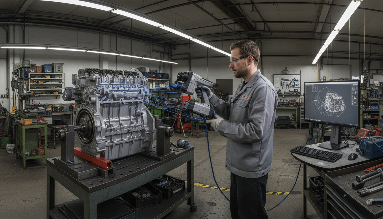
When a mining operator needs to retrofit collision avoidance systems onto a fleet of haul trucks, or a transport company requires reverse engineering of discontinued automotive components, measurement accuracy becomes non-negotiable. Traditional measurement methods – tape measures, callipers, and manual documentation – introduce human error, consume excessive time, and often fail to capture the complex geometries of modern industrial equipment. This is where 3D laser scanning technology transforms the engineering process.
3D scanning captures a dense set of surface points. The live 3D services page lists scanning for measurements and detail. It does not publish a millimetre tolerance. For industries where dimensional errors translate directly to safety risks, project delays, and cost overruns, this precision is a fundamental requirement.
What Makes 3D Scanning Essential for Modern Engineering
Engineering projects in mining, heavy transport, and industrial manufacturing demand measurement accuracy that manual methods simply cannot deliver consistently.
Why Traditional Measurement Methods Fall Short
A mine-spec vehicle fitout might require precise spatial data for mounting brackets, wiring routes, and equipment clearances across dozens of vehicles. A single measurement error compounds across the entire fleet, resulting in rework, delays, and compromised safety margins.
3D laser scanning can capture a lot of spatial data in one session. Gaps still happen if a surface is missed. Rather than measuring individual dimensions and hoping they align correctly in the final design, engineers work with a complete digital twin of the physical asset. This approach reveals interferences, clearance issues, and spatial conflicts before fabrication begins – when corrections cost hours rather than weeks. Vibration data analysis can sit beside a later mount check.
From Manual Measurement to Digital Twins
The technology proves particularly valuable for complex geometries that resist traditional measurement. Curved surfaces, irregular shapes, and assemblies with limited access become straightforward to document. Laser scanning can cover a large item faster than a tape measure. It still needs a clear line of sight and a later check.
EIG’s 3D services apply this capability across automotive component scanning, industrial equipment measurement, and as-built documentation projects – connecting precise spatial data directly to the design and fabrication workflows that follow.
How LiDAR Spatial Mapping Technology Works
LiDAR (Light Detection and Ranging) systems emit laser pulses that bounce off surfaces and return to the scanner. By measuring the time each pulse takes to return, the system calculates precise distances to millions of points across the target surface. The result is a point cloud – a dense collection of spatial coordinates that collectively represent the three-dimensional form of the scanned object.
Point Cloud Data Capture and Processing
Modern 3D laser scanning technology captures vast numbers of points per second depending on equipment and application requirements. For industrial equipment measurement, this density ensures that even small features – bolt holes, mounting surfaces, weld seams – appear clearly in the digital model. Achievable accuracy typically ranges from ±1 mm to ±3 mm for standard industrial work, with metrology grade scanning systems reaching tighter tolerances for precision applications.
The scanning process is non-contact and non-destructive. Unlike traditional measurement that requires physical access to every surface, laser scanning can work at a standoff, so some surfaces can be captured without stripping the machine. This capability proves critical when scanning operational equipment, hazardous areas, or components that cannot be disassembled for measurement.
From Raw Data to Usable Engineering Formats
Once captured, point cloud data undergoes processing to remove noise, align multiple scan positions, and generate usable formats. Software converts the raw points into mesh models, CAD surfaces, or direct dimensional measurements depending on project requirements. This processed data integrates seamlessly with engineering workflows, feeding directly into design software, analysis tools, and fabrication systems.
Applications in Automotive Component Scanning
Automotive component scanning addresses several persistent challenges in vehicle engineering and manufacturing.
Reverse Engineering and Custom Vehicle Modifications
Reverse engineering represents one of the most common applications. When original CAD data is unavailable – whether for discontinued parts, legacy vehicles, or components from overseas manufacturers – 3D scanning recreates accurate digital models from physical samples.
This capability supports custom vehicle modifications common in mining and transport operations. Rather than working from manufacturer specifications that may not reflect as-built conditions or local modifications, automotive component scanning captures the actual vehicle geometry. The resulting data ensures that custom brackets, wiring harnesses, and equipment mounts fit correctly on the first attempt.
For mixed fleets with different modification histories, this scanning process creates a documented baseline. Engineered Installations Group keeps that scan with the same design pack. Each vehicle’s unique configuration becomes part of a digital asset library, supporting maintenance planning, parts procurement, and future modification projects.
Quality Control and Dimensional Accuracy Verification
Dimensional accuracy verification is a critical quality control application. A single scan compares the physical part against the CAD model, generating colour-mapped deviation reports that highlight areas outside tolerance. This process identifies manufacturing defects, material deformation, and assembly errors before components reach the installation stage.
Metrology grade scanning standards apply where component tolerances directly affect functional performance – precision-machined surfaces, bearing seats, or interface features that must align with mating components. The combination of high-density point cloud capture and rigorous deviation analysis ensures that manufactured parts meet design intent before they are committed to an assembly.
Industrial Equipment Measurement Applications
Large-scale mining and industrial equipment presents measurement challenges that dwarf automotive applications. A haul truck, excavator, or processing plant component might span tens of metres and operate in environments where extended downtime for measurement is economically unacceptable. 3D laser scanning technology addresses these constraints directly.
Large-Scale Mining Equipment
Dimensional accuracy verification for custom fabrication projects relies on accurate spatial data. When fabricating mounting frames, structural supports, or equipment enclosures for existing machinery, the margin for error is minimal. A support frame that does not align with mounting points requires expensive rework and extended equipment downtime. 3D laser scanning captures existing equipment geometry with precision sufficient that fabricated components fit correctly during the first installation attempt.
As-Built Documentation and Maintenance Tracking
As-built documentation for plant and facility upgrades provides another valuable application. Mining operations frequently modify processing plants, material handling systems, and infrastructure over their operational life. Original design drawings become outdated as changes accumulate. Before planning expansions or equipment upgrades, operators need accurate information about current conditions. Industrial equipment measurement creates this baseline, documenting existing layouts, clearances, and spatial relationships.
The technology also supports maintenance and inspection workflows. Periodic scans of critical equipment can show later shape change. Customized kits still need that scanned shape before later kits are copied. Vibration data analysis can sit beside a mount check. A conveyor frame showing progressive deflection or a vessel exhibiting unexpected deformation becomes visible in the scan data long before it reaches a critical threshold.
The Process: From Scan to Usable Data
3D scanning projects follow a structured workflow that transforms physical assets into actionable engineering data. The process begins with project scoping – defining measurement accuracy requirements, deliverable formats, and specific features of interest. Workshop installation services give a controlled place for a first fit after the scan.
Field Data Capture and Registration
Field data capture typically requires multiple scan positions to ensure complete coverage. Registration targets – distinctive markers placed around the scan area – allow software to align multiple scan positions into a unified coordinate system. For large equipment or complex sites, a single project might involve many individual scan positions.
Quality verification occurs during capture, not after. Vibration data analysis can sit beside a later mount check. Checking point cloud density, identifying areas requiring additional scanning, and confirming adequate overlap between positions prevents discovering gaps during later processing phases. This real-time verification is particularly important for remote site work. On-site field services can do a later check if a surface was missed.
Data Processing and Deliverable Formats
Raw point cloud data undergoes processing before becoming useful for engineering work: spurious points are removed, multiple scans are aligned, and the dataset is optimised for handling. The processed point cloud then converts into the required deliverable format.
Deliverable formats vary based on application. Engineers working on structural modifications might receive mesh models compatible with finite element analysis software. Designers creating custom components need CAD surfaces they can work in. Customized kits still need that scanned shape before later kits are copied. Vibration data analysis can sit beside the scan when a mount is being checked. Quality control applications generate dimensional deviation reports comparing scan data against nominal CAD models. The flexibility to produce multiple deliverable types from a single scan dataset maximises the value of captured data.
Integration With Engineering Analysis Services
The true power of 3D scanning emerges when measurement data feeds into broader engineering workflows. Dimensional accuracy verification provides the foundation, but the captured geometry enables analysis and design work that would be impractical with traditional measurement.
3D Scan Data and Finite Element Analysis
FEA performed on scan-derived geometry reflects actual as-built conditions rather than idealised design geometry, producing results that account for real-world variations and existing modifications. When analysing structural modifications to existing equipment – adding mounting points to a vehicle frame, reinforcing a support structure, or evaluating load paths through complex assemblies – the analysis is only as good as the geometric model. EIG’s electrical engineering solutions team also draws on scan data for custom wiring harness routing, ensuring cable paths are designed against actual vehicle geometry rather than nominal drawings.
System Design and Installation Planning
When integrating multiple systems onto a vehicle or piece of equipment – collision avoidance sensors, autonomous operation systems, communication equipment – designers must account for existing components, clearance requirements, and access needs. Working from scan data helps new systems get drawn against the current shape, that cable routes follow practical paths, and that maintenance access remains feasible. EIG’s on-site installation teams use pre-captured scan data to prepare for remote site installations, arriving with components designed against verified geometry rather than nominal drawings. EIG’s system design process uses scan-derived geometry as its spatial baseline, eliminating the information gaps that arise when design work proceeds from approximate manual measurements.
Why Measurement Precision Matters in Mining and Heavy Industry
Dimensional errors in mining and heavy industrial contexts carry consequences that extend well beyond simple rework costs. When a custom-fabricated mounting frame does not align with equipment attachment points, the project faces delays measured in weeks. The equipment remains out of service while corrections are designed, fabricated, and installed. For production equipment in mining operations, this downtime translates directly to lost output and revenue.
Safety considerations add another dimension. Load-bearing changes still need their own engineering check. A scan is geometry. It is not a certificate.
Efficiency gains from accurate as-built documentation compound across project lifecycles. A mining operation planning multiple equipment modifications over several years benefits from maintaining a digital asset library of 3D scan data. Each subsequent project references existing spatial data rather than conducting new site measurements, reducing project lead times and eliminating repeated mobilisations. Contact us to check how 3D scanning can support the current measurement or documentation job.



Leave A Comment