
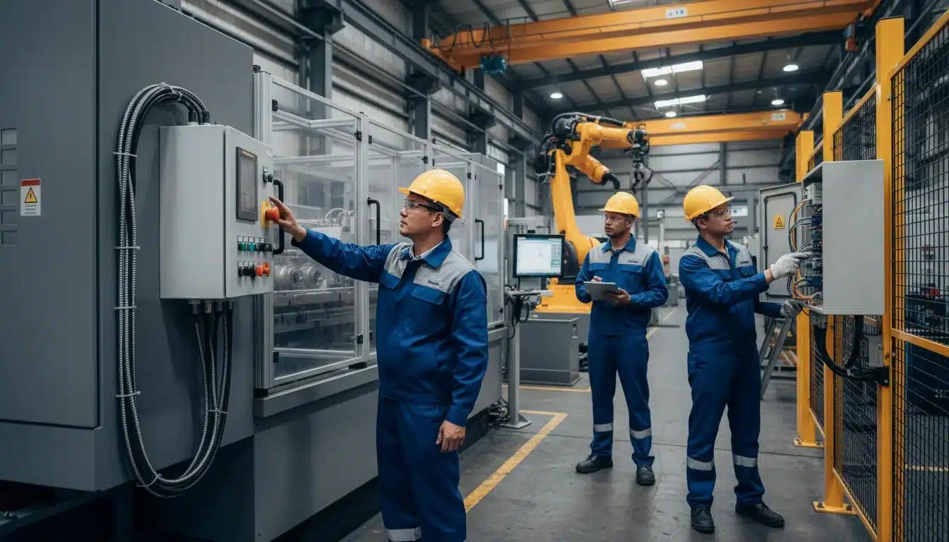
When a loader operator activates the emergency stop during a tyre change, that single action must instantly and reliably de-energise every hazardous function on the machine. No exceptions, no delays, no single points of failure. This is not just good practice, it is a legal requirement under AS4024 functional safety standards, and the difference between a controlled shutdown and a serious incident.
Heavy equipment operating in Australian mines and industrial facilities presents unique safety challenges. A haul truck, an underground loader, or a surface drill rig all share common ground: they are complex machines with multiple energy sources, hydraulic systems operating at extreme pressures, and electrical circuits controlling critical functions. When something goes wrong, or when maintenance requires isolation, the emergency stop and safety interlock systems become the last line of defence between workers and serious injury.
Understanding AS4024 Functional Safety Requirements
AS 4024 is one Australian framework used when designing, implementing and maintaining machinery safety systems. These standards are built on decades of incident analysis and engineering best practice, specifically adapted for Australian conditions and regulations.
Performance Levels, SIL Ratings, and Category Structures
The standard defines Performance Levels (PL) ranging from PLa to PLe, with PLe representing the highest level of risk reduction. For most heavy equipment safety systems, particularly emergency stops on mining vehicles, PLd or PLe is typically required. This translates to a probability of dangerous failure that must be extraordinarily low: the system must be reliably safe across years of continuous operation in harsh conditions.
Safety Integrity Levels (SIL), drawn from IEC 61508, provide another framework often used alongside AS4024. SIL ratings (1 through 4) quantify the reliability of safety functions. For heavy equipment emergency stops, SIL 2 or SIL 3 is common, depending on risk assessment outcomes.
Category ratings (B, 1, 2, 3, and 4) describe the architectural structure of safety-related control systems. Category 3 and 4 systems incorporate redundancy and diagnostic coverage, essential features for heavy equipment safety systems where single-point failures are unacceptable.
Emergency Stop System Design Fundamentals
Designing an emergency stop system that meets these functional safety requirements demands more than installing a red mushroom button and wiring it to a contactor. The architecture must account for component failures, environmental conditions, and human factors while maintaining reliability over years of operation in harsh conditions.
Redundancy and Fail-Safe Architecture
Dual-channel monitoring is a common backbone for emergency stop system design under that framework. Two independent circuits monitor the emergency stop status, each capable of initiating a safe shutdown independently. If either channel detects an emergency stop activation, or if the channels disagree with each other: the system enters a safe state.
This cross-checking happens continuously, typically multiple times per second. A microprocessor-based safety controller compares the status of both channels. Agreement between channels confirms normal operation. Disagreement triggers an immediate shutdown and flags a diagnostic fault.
Fail-safe design aims for a single component failure to leave the machine in a safe state, not a hazardous one. Contactors are normally energised during operation and de-energise to stop. Relay contacts are arranged so that open circuits, broken wires, or failed components cause shutdowns rather than allowing continued operation. This positive-mode operation is non-negotiable for AS4024 compliance.
Diagnostic Coverage and Fault Detection
Diagnostic coverage refers to the system’s ability to detect its own faults. High diagnostic coverage, typically 90 to 99 per cent for Category 3 and 4 systems, means that most dangerous failures are detected before they can compromise safety.
Continuous monitoring includes checking for short circuits, open circuits, cross-faults between channels, and component degradation. When a fault is detected, the system responds according to its programming, usually an immediate safe shutdown and a lockout preventing restart until the fault is cleared.
Testing and validation procedures verify that diagnostic functions work as intended. This includes deliberately introducing faults during commissioning to confirm the system responds correctly. Documentation of these tests forms part of the compliance record.
Safety Interlock Design Principles
While emergency stops provide immediate shutdown capability, safety interlocks prevent hazardous operations from starting or continuing when conditions are unsafe. On heavy equipment, interlocks might prevent hydraulic functions while maintenance guards are open, disable tramming when the drill mast is raised, or lock out high-voltage systems during battery changes.
Logical Sequencing and Tamper Resistance
Logical sequencing is meant to keep operations in a safe order. A loader’s tray cannot tilt unless it is raised above a minimum height. A haul truck’s body cannot lower unless the tailgate is confirmed closed. These sequences are hardwired into the safety logic, not dependent on operator action or software that might be bypassed.
Preventing inadvertent bypassing is critical to effective safety interlock design. Interlock switches must be tamper-resistant, positioned where they cannot be easily defeated, and monitored for fault conditions. Magnetic switches, coded safety switches, or trapped-key systems provide higher security than simple limit switches that can be held closed with wire ties or tape.
Integration With Machine Control Systems
Integration with machine control systems requires careful interface design. The safety system must be independent, it cannot rely on the main control system for safety-critical decisions, but it must also communicate status and faults to operators and maintenance systems. This typically involves separate communication channels with defined protocols.
SIL rated control circuits that interface with standard machine control architecture must maintain their rated integrity at the interface boundary. The design should keep a fault in the standard control system from propagating into the safety system. System design treats that interface as its own job.
Electrical Schematic Design for Safety Systems
Electrical schematic design for safety systems follows strict conventions that differ from standard control schematics. Electrical engineering solutions keep those safety circuits off the ordinary control drawing. Every component, connection, and circuit path must be documented with clarity that survives years of maintenance, modifications, and personnel changes.
Circuit Design Standards and Component Selection
Circuit design standards require that safety circuits are clearly distinguished from non-safety circuits. Engineered Installations Group keeps that split in the same design pack. This includes physical separation where practical, distinct wire colours, and unambiguous labelling. Safety circuits use dedicated terminal blocks, separate from standard control circuits, to prevent accidental cross-connection during maintenance.
Component selection for safety-rated applications means choosing devices specifically certified for safety functions. A standard relay might be electrically identical to a safety relay, but the safety-rated device has been tested for failure modes, contact welding resistance, and mechanical endurance under fault conditions. Certification bodies like TÜV confirm suitability for specific Performance Levels.
Documentation requirements extend beyond circuit diagrams. A complete safety system package includes functional descriptions, risk assessments, failure modes and effects analysis (FMEA), validation test results, and maintenance procedures. This documentation supports later checks and provides the information needed for ongoing operation. Finite element analysis can sit beside that pack when a mount or guard is being changed.
Implementation on Mine-Spec Vehicles
Applying these functional safety principles to mobile heavy equipment introduces additional complexity. Unlike fixed industrial machinery, mine-spec vehicles operate in environments with extreme vibration, temperature swings, dust ingress, and physical impacts that can compromise safety systems if not properly designed.
Environmental and Vibration Challenges for Mobile Equipment
Specific challenges for mobile equipment include maintaining electrical connections under constant vibration, protecting sensitive electronics from electromagnetic interference generated by large motors and radio equipment, and ensuring that safety switches remain properly aligned despite chassis flexing and suspension movement.
Environmental considerations for harsh mining conditions mean specifying components with appropriate ingress protection ratings, typically IP67 or higher for external devices, and ensuring that enclosures, connectors, and wiring withstand the physical environment. Conformal coating, sealed connectors and vibration-resistant terminal blocks are common site requirements. Vibration data analysis can show whether a switch or enclosure is being shaken out of alignment.
Power Supply and Cable Routing Considerations
Power supply considerations matter because safety systems require clean, stable power independent of the main vehicle electrical system. Dedicated power supplies with battery backup ensure that safety functions remain operational even if the main electrical system fails. This redundancy is particularly important for emergency stops, which must function regardless of other system states.
Safety system installations are best performed in workshop installation services environments where wiring harnesses can be routed with full access, properly separated from power and control wiring, and verified against schematics before the vehicle is returned to service. Running dedicated safety system harnesses on older vehicles often requires substantial disassembly, a task that is practical in a controlled workshop but significantly more difficult on remote mine sites.
Human Factors in Emergency Stop Placement
Human factors influence design choices that go beyond pure compliance with the standard. Emergency stop buttons must be positioned where operators can reach them instinctively under stress, without looking, from normal operating positions. The buttons must be large enough to activate reliably while wearing gloves, distinctively shaped for tactile recognition, and coloured red with yellow backgrounds per the relevant standards.
Multiple emergency stop locations on large equipment give workers more than one place to reach a stop. The logic connecting multiple stops must ensure that activation from any location produces the same immediate, complete shutdown response.
Testing, Validation, and Commissioning
Pre-Commissioning Verification and Functional Testing
Pre-commissioning verification confirms that the system is built according to design. This includes checking every wire connection against schematics, verifying component ratings and certifications, confirming proper labelling, and testing insulation resistance and circuit continuity.
Functional testing protocols check each safety function under controlled conditions. 3D services can record as-fitted button and switch positions before a second machine is copied. Emergency stop system design validation includes activating buttons from every location, testing interlocks by opening guards and operating switches, challenging diagnostic functions by introducing deliberate faults, and measuring response times to confirm they meet design specifications.
Documentation, Certification, and Ongoing Compliance
Documentation and certification requirements vary by jurisdiction and site-specific regulations, but typically include test results, as-built drawings, component certifications, maintenance procedures, and operator instructions. This package supports later checks.
A safety system that passed commissioning can drift if inspection and repair stop. Regular inspection schedules, typically monthly or quarterly depending on operating conditions, verify that emergency stop buttons activate smoothly, interlock switches align correctly, and diagnostic indicators function. On-site installation support teams performing scheduled maintenance verify safety system integrity as part of each inspection, identifying issues before they affect compliance or create risk.
Recertification after modifications is essential. Adding new equipment, changing sequences, or replacing components can affect safety system performance. Customized kits help keep later machines closer to the first agreed layout. Any change requires evaluation to determine whether it impacts the safety function, and if so, appropriate testing and documentation updates.
Integration With Collision Avoidance and Autonomous Systems
Modern heavy equipment increasingly incorporates collision avoidance systems and autonomous or semi-autonomous operation capabilities. Integrating these advanced systems with emergency stop and safety interlock functions creates additional design challenges while offering opportunities for enhanced safety.
Automatic Emergency Stops and Autonomous Safety Logic
Collision avoidance systems must interface with emergency stop systems so that detected hazards can trigger automatic emergency stops when appropriate. This requires careful logic design to distinguish between situations requiring immediate stops versus warnings to operators. False positives that trigger unnecessary emergency stops reduce productivity and may lead operators to distrust or bypass the system, a dangerous outcome that undermines the purpose of the safety system entirely.
Autonomous systems add another layer of complexity, often requiring SIL rated control circuits with more sophisticated diagnostic coverage because human oversight is reduced or absent. When no operator is present to activate an emergency stop, the safety system must incorporate additional sensors and logic to detect hazardous conditions automatically. This might include tilt sensors, pressure monitoring, temperature limits, or communication loss detection. Autonomous equipment safety systems typically require PLe and more sophisticated diagnostic coverage because human oversight is reduced or absent.
Practical Considerations for Ongoing Maintenance
Fault logging and analysis provide insight into system health and potential issues before they compromise safety. Modern safety controllers record every activation, every diagnostic fault, and every test cycle. Analysing this data reveals patterns, a particular switch failing more frequently, a circuit showing intermittent faults, or a component approaching end of life. Preventive maintenance based on this monitoring prevents failures before they cause downtime or compliance issues.
Obsolescence management is critical for equipment with service lives exceeding 20 years. Designing safety systems around components likely to remain available, or ensuring that suitable replacements can be substituted without complete redesign, prevents situations where a single failed component renders an entire machine non-compliant.
Local supply and support matter for remote mining operations. Components available through Australian distributors with local stock reduce downtime when failures occur. Technical support from suppliers familiar with AS4024 functional safety requirements and Australian mining conditions adds practical value beyond component supply alone.
For heavy equipment safety system projects, whether new installations or upgrades against current standards, Contact us to check the current scope.



Leave A Comment