
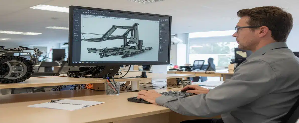
Mobile mining equipment operates in environments where operator safety depends on engineered protection systems. Roll-over protective structures and falling object protective structures form the last line of defence when incidents occur, yet designing these systems to meet Australian standards presents complex engineering challenges. Finite element analysis services have transformed how mining operators and equipment manufacturers approach compliance, reducing costs while improving structural performance.
Why ROPS and FOPS Matter in Australian Mining
Regulatory Requirements Under AS2294
Australian mining operations require roll-over protective structures and falling object protective structures on mobile equipment under AS2294 safety compliance standards. These regulations specify load-bearing requirements, deformation limits, and testing protocols that protective structures must satisfy before equipment enters service at mine sites.
The consequences of inadequate protection extend beyond regulatory penalties. When mobile equipment experiences roll-over events or falling object impacts, the structural integrity of ROPS and FOPS directly determines operator survival outcomes. Mine site procurement teams routinely reject equipment lacking proper certification, creating operational delays and financial losses for contractors.
Autonomous Equipment and Evolving Certification Demands
AS2294 safety compliance requirements have tightened as autonomous and semi-autonomous systems become more prevalent. Even remotely operated equipment requires protective structures meeting the same standards as operator-present machines, since maintenance personnel and supervisors still access cabins during servicing and troubleshooting activities.
The Engineering Challenge of Protective Structure Design
Balancing Strength, Visibility, and Weight
Designing compliant roll-over protective structures involves balancing competing requirements. AS2294 standards specify minimum energy absorption levels and maximum allowable deflection under load, while operators demand unobstructed sight lines for equipment operation. Adding structural members to increase strength often reduces visibility, creating hazards during normal operation.
Weight presents another constraint. Heavy protective structures increase overall vehicle mass, reducing payload capacity and increasing fuel consumption across fleet operations. Mining operators calculate total cost of ownership over equipment lifecycles measured in decades, making incremental weight additions economically significant.
Material selection affects both performance and cost. High-strength steel alloys offer superior load-bearing capacity in smaller cross-sections but increase fabrication complexity and material expenses. Standard structural steel reduces costs but requires larger members to achieve equivalent strength, impacting sight lines and weight targets.
Mounting Point Design and Load Transfer
Mounting point design proves critical for load transfer. Protective structures experience extreme forces during roll-over events, and inadequate attachment to the vehicle chassis can cause catastrophic failure regardless of the structure’s inherent strength. Engineered Installations Group encounters these design challenges across mine-spec vehicle programs, where protective structure integration affects electrical system routing, hydraulic line placement, and operator ergonomics.
How Finite Element Analysis Validates Structural Performance
From Physical Prototype Destruction to Digital Simulation
Finite element analysis services provide digital simulation of physical testing scenarios specified in AS2294 standards. Engineers create detailed computer models of proposed ROPS and falling object protective structures designs, then apply virtual loads matching certification test requirements. The software calculates stress distribution, deflection patterns, and potential failure points throughout the structure.
This simulation-based approach reveals structural behaviour under extreme loads without destroying physical prototypes. Traditional compliance pathways required fabricating full-scale structures, mounting them to test fixtures, and applying destructive loads until failure occurred or compliance was demonstrated. Each design iteration demanded new fabrication, with costs accumulating when initial designs failed to meet standards.
FEA shifts this iteration process into the digital domain. Engineers modify geometry, adjust material specifications, or relocate reinforcements within the computer model, then re-run simulations to evaluate performance changes. The analysis identifies stress concentrations that may not be obvious from visual inspection or traditional hand calculations – weld locations, corner radii, and cross-section transitions often develop localised stress peaks that can initiate fatigue cracks or sudden failures.
How the Analysis Calculates Compliance
Colour-coded stress maps reveal which areas approach material yield limits and which regions remain under-utilised. This visualisation helps engineers understand load paths through the structure and identify opportunities for optimisation. Deflection analysis compares structural deformation against allowable limits, providing clear pass/fail indicators for compliance assessment against AS2294 deformation thresholds.
Safety factors account for uncertainties in material properties, fabrication quality, and loading conditions. FEA results inform appropriate safety factor selection based on stress distribution uniformity and deflection behaviour.
The FEA Process for ROPS and FOPS Compliance
Initial Design Assessment
The finite element analysis process begins with accurate geometry models. Engineers import CAD data from the proposed protective structure design, ensuring all structural members, connection plates, and mounting points are represented with correct dimensions. Material property definition follows – the analysis software requires elastic modulus, yield strength, and Poisson’s ratio values matching the actual steel grades planned for fabrication.
Mesh generation divides the continuous structure into thousands of small elements. Finer meshes produce more accurate results but require longer computation times. Engineers balance accuracy requirements against project schedules when selecting mesh density. Boundary conditions replicate physical test setups, constraining the structure’s mounting points to match how the protective structure attaches to vehicle chassis during actual testing.
Load Case Simulation Under AS2294 Standards
AS2294 standards specify multiple load cases representing different failure scenarios. Roll-over events apply horizontal forces simulating ground impact during vehicle overturn. ROPS certification testing load cases include specific force magnitudes and application points that the FEA model must replicate precisely.
The software applies these virtual loads and calculates resulting stress distribution throughout the structure. Deflection analysis at standard-specified measurement points provides clear compliance indicators – the structure must not collapse into the operator’s survival space under the applied loads.
Design Iteration and Optimisation
Initial designs rarely satisfy all requirements simultaneously. The first simulation might reveal excessive deflection in one load case while showing over-designed, unnecessarily heavy members in another area. Structural reinforcement options include increasing member thickness, adding gusset plates at high-stress joints, or changing cross-section geometry from rectangular to tubular profiles. System design expertise helps evaluate these trade-offs within the broader context of vehicle functionality and operator requirements.
Weight reduction opportunities emerge when simulation reveals structural members with consistently low stress levels. These optimisations lower manufacturing costs and improve vehicle fuel efficiency across operational lifecycles. Documentation for certification authorities compiles simulation methodology, material specifications, load case definitions, and results summaries.
When Physical Testing Still Matters
Validation Testing on Production Units
Finite element analysis services don’t eliminate physical testing requirements entirely. AS2294 compliance pathways typically require validation testing on at least one production unit, even when FEA predicts satisfactory performance. Strain gauges measure deflection at critical points, while inspectors observe failure modes and load-bearing behaviour. Results should align closely with FEA predictions, confirming the model’s accuracy and validating the analysis methodology.
Combined approaches offer cost-effective compliance for fleet programs involving multiple similar units. Engineers perform comprehensive FEA on the initial design, then conduct physical validation testing on the first production unit. Subsequent units receive certification based on the validated FEA model, provided fabrication follows documented procedures and quality checks confirm consistency with the tested prototype.
Novel Designs and Non-Standard Load Cases
Scenarios involving novel materials, unusual geometry, or non-standard load cases may require more extensive physical testing. Certification authorities exercise discretion when evaluating compliance pathways, and they may mandate additional validation when designs deviate significantly from established patterns. FEA still provides value in these situations by reducing the number of physical prototypes required and guiding test setup design.
Integration With Vehicle Fitout Programs
Electrical Routing and Collision Avoidance Sensor Placement
Protective structure installation intersects with numerous other vehicle systems. Electrical engineering solutions for mine-spec vehicles must route wiring harnesses around ROPS mounting points while maintaining proper clearances and strain relief. Collision avoidance system sensors require unobstructed mounting locations that don’t compromise structural integrity or create new impact hazards.
Workshop Installation and Field Retrofit Considerations
Workshop installation of certified ROPS and FOPS assemblies demands precise alignment with chassis mounting points. Bolt torque specifications, hole alignment tolerances, and weld quality all affect the structure’s ability to perform as designed during impact events. Workshop installation services coordinate protective structure fitment with broader vehicle preparation activities, ensuring proper sequencing of structural, electrical, and hydraulic system installations.
Field retrofit considerations arise when mining operators upgrade existing fleet assets with improved protective structures. Space constraints, existing equipment interference, and operational downtime limitations complicate retrofit projects. FEA helps evaluate whether existing chassis mounting points provide adequate strength for upgraded structures or require reinforcement before installation.
Conclusion
The investment in FEA-based design validation pays returns throughout equipment lifecycles. Structures engineered to precisely meet AS2294 safety compliance standards without over-design reduce vehicle weight and fuel consumption across years of operation. Avoiding failed certification tests eliminates expensive fabrication rework and project delays. Most significantly, properly designed and validated protective structures fulfil their ultimate purpose when incidents occur.
Mining operators planning fleet expansions, equipment upgrades, or new vehicle procurements should engage engineering partners early in project timelines. Early involvement allows structural design to inform rather than constrain vehicle specifications, and it provides adequate schedule margin for thorough analysis, iteration, and certification processes. Call +61 (08) 9419 7318 to discuss ROPS and FOPS compliance requirements for your mining fleet.



Leave A Comment