
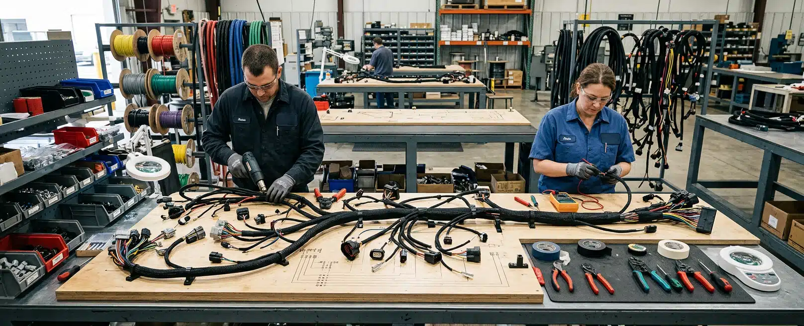
A factory loom is built for the vehicle the OEM signed off, not for every later variant in the yard. Custom wiring harness manufacturing starts when the electrical job has changed: extra loads, a new control architecture, a body the chassis never carried, or a route the original harness cannot take without damage.
If factory circuits still match the loads, the environment, and the way your workshop traces a fault, keep them. A sound loom still carries pinouts and diagnostic habits the dealer already uses. You need a custom harness when the system you must fit cannot be built, protected, or repaired from the factory drawing set.
Our work is to turn that requirement into a design someone can manufacture and service. We produce the schematic and build records so a fabrication team can cut and terminate the assembly, and so a technician can trace the same identifiers later.
When The Factory Harness Still Holds
OEM harnesses are sized for a known load set, a known route, and a known connector family. On a prime mover that still runs factory lighting, engine management, and trailer plugs, that design remains a sound match for those circuits. It was validated with the vehicle, and the parts channel already understands it.
When The Vehicle Stops Being The Standard Article
The electrical job changes when the vehicle stops being that standard article. Mine-spec trucks, specialised agricultural machines, and custom industrial vehicles often carry cameras, proximity detection, auxiliary lighting, hydraulics, telemetry, or traction gear the chassis maker never bundled.
Those additions mean the vehicle now has a different circuit list. If a documented accessory interface or a spare OEM way can carry a protected extra load, use it. Custom work is warranted when you need new distribution, new protection, a new chassis route, or a connector the factory harness does not give you.
Design For Manufacture, Not A Shelf Loom
When you work with Engineered Installations Group, we produce design for manufacture: engineering-grade electrical schematics for machinery systems and custom wiring harnesses, plus the records a builder needs to cut, terminate, and install without guessing.
Our harness design output includes precise cut lists, detailed material specifications as a bill of materials, and exact termination instructions. Without lengths, terminals, seals, and pin maps, those details get decided on the bench. Fleet builds can then diverge from vehicle to vehicle, and the next inspection has no single product to follow.
We work directly with OEMs and fleet operators on heavy mining, specialised agricultural, and custom industrial fleets. Electrical engineering and system design come first. Workshop or field installation follows when the vehicle must be fitted or inspected. Who cuts the wire depends on the project. We design so a fabrication team can manufacture and install without fighting the chassis.
Freeze The Variant Before You Freeze Lengths
Two vehicles with the same badge can hide different option codes, body-builder looms, and old aftermarket branches. Freeze the variant before you freeze lengths and cavities. A harness drawn for a truck you have not identified will be adapted during install with extra joints.
Loads And Duty Cycle First
Start with the circuit list rather than colour codes. Document OEM loads you will keep, equipment you will add, and spare capacity you truly intend to use. Continuous current and peak current are different figures. A lighting bank that runs for hours is not the same duty as a solenoid that pulls hard for a second.
Duty cycle drives cable size, protection, and heat at the termination. If you size from the original factory loads, connectors on the added circuit can run hotter than they were sized for. If you jump several sizes without checking the route, the extra bulk can be hard to clamp and hard to repair. Size from measured or specified draw, run length, and the voltage the machine actually uses.
Heavy transport electrical systems commonly run 12 V or 24 V for control and lighting, with higher voltage where traction or charging architecture requires it. Long chassis runs at low voltage waste more of the supply in the cable than a short dash run of the same cross-section. Size for the path you will actually pull.
Protection belongs with the new load. Borrowing an OEM fuse for an auxiliary hydraulic pack can starve factory circuits or leave the added load unprotected. Separate, documented protection belongs in the harness design so it is present before install.
Unlabelled extra cores in the wrap are easy to treat as spare capacity and then crimp onto the wrong circuit. If a later camera set or control module is a real plan, reserve a named cavity, a protected way, or a junction that can be extended without opening the whole loom.
Routing With The Mechanical Design
A schematic that cannot be pulled through the vehicle is not a manufacturable harness. The loom has to be clamped, protected, and kept off exhausts, prop shafts, articulation points, and covers a fitter will never remove during a fault.
Our system integration work sets that path with the mechanical design, so mounts, clamps, and protection are decided while the structure is still open to change. Electrical and control gear has to be mounted so it can take shock and vibration. If the machine already shows how that chassis moves in service, vibration data analysis helps decide whether a module needs a damped mount rather than a hard clamp on the rail.
Power and communication architecture still has to be designed so it does not harm factory circuitry. Safety circuits such as emergency stops and interlocks still have to be designed against functional safety requirements. Where a new bracket or enclosure carries that gear, finite element analysis checks stress and deflection on the mount before we lock the harness to it.
Detailed design includes 3D routing for harness and fluid lines, schematics, and mechanical assembly drawings. That is how a loom stays out of a heat source or a pinch point, and how sleeving, grommets, and service loops get onto the bill of materials instead of being improvised with cable ties. When the chassis in the yard does not match the model, 3D scanning of the actual machine gives us the clearances we will pull through.
Separate The Rail Run From The Cab Run
A chassis-rail run and a cab run are different constructions. The rail needs abrasion protection and clamp spacing that survive corrugations and payload shift. The cab may need a break for dash work. Write both so the builder does not wrap the truck as one bundle.
Keep High-Voltage Routing Segregated
High-voltage routing on electrified mobile equipment needs its own segregation, identification, and isolation. We design electrical architecture and high-voltage harness routing for electrified excavators and other mobile assets as part of that system work, together with the low-voltage control and safety circuits those machines still need.
Materials Match The Location
Insulation, terminals, seals, and covers follow the environment on that route. An engine bay, a wet chassis rail, and a protected cabinet are not one specification. A connector that is easy to probe in a workshop can be wrong in a wheel-arch that packs mud.
Insulation must take the heat and fluids at the location. Softer commodity covering can move, crack, or abrade under heat cycling and stone wear. Tougher insulation, or a thinner wall in a tight pass, is chosen on the bill of materials against that duty.
Connectors are chosen for current, vibration, sealing, and how often someone will unmate them. A sealed chassis face is a different part from a bulkhead inside a cabinet. If the joint is a service break, mating life matters. If it should stay closed for the life of the body, strain relief and sealing matter more.
The factory plug is correct for the factory circuit. Your added circuit may need a different cavity count, seal, or break. Put the part number on the bill of materials and the pin map on the schematic so the next inspection does not start with a guess.
Interfaces With The Vehicle You Already Have
A custom harness on a heavy vehicle often joins new equipment to the factory electrical system rather than replacing it. We add power, grounds, and communication paths for new equipment while factory circuits keep the job they were signed off to do. That only works if we know how the vehicle already distributes power and returns to ground.
New safety equipment, cameras, and fleet systems often need a clean supply and, sometimes, vehicle data. Tapping with scavenged earths on a painted rail is a common source of intermittent faults that appear months later, often away from a workshop. Designed branches and documented grounds give the next technician a point they can find and test.
Where the harness sits inside a wider mechatronic package, power distribution, communications, and safety circuits are designed with the mounts. Emergency stops and interlocks still have to make sense when someone isolates the machine, so they are designed as safety circuits with that architecture.
Prefer The Factory Accessory Interface
Specify the ground point, the terminal, and how it will be inspected. A convenient bolt that later disappears under paint or corrosion can look like almost any other electrical complaint on the truck. If the OEM publishes an accessory interface, prefer it. Custom branches should start where the factory system is meant to be extended.
Fit The Harness Around Support Ute Payload
Light support utes in the same fleet often take trays, canopies, lighting, jumpstart gear, and cameras that change payload and ride height. On Australian utes, braking and suspension upgrades sit in that payload conversation. The harness still has to clear the tray, the canopy mounts, and the ride height those upgrades produce, rather than being taped across a body that will move once the vehicle is loaded.
Make It Diagnosable
A harness that can be built once but cannot be traced is a problem on a heavy vehicle. Shutdown windows and remote faults depend on finding a pin, isolating a branch, and replacing a damaged section without stripping the chassis.
Wire numbers, connector cavities, and termination instructions should be what the fitter sees on the loom, not only on a drawing in the office. If the built assembly and the pin map disagree, the next technician is working from two different products.
Inspection access is a routing decision. A diagnostic break buried behind a tank, or a splice lost in a wrapped bundle, makes tracing harder and can mean cutting the wrap to find the joint. Labelled breaks and a bill of materials that names the terminal let a condition audit test a circuit instead of opening the loom.
Decide Workshop Or Field Before You Hide A Break
If the vehicle can come to Forrestdale, we carry out workshop installation and the checks that go with it. If the machine cannot leave the site, we carry out on-site installation and inspect the asset. Either path still needs a design that says what to look at, and a break that can be reached in that location.
Aftercare works when the circuit can be identified and tested. Condition and performance audits, scheduled servicing, and installation aftercare need labelled breaks and a named terminal. An undocumented wrap leaves those checks without a clear test point.
From Requirements To A Builder
Feasibility captures the electrical job, performance targets, and early risk. Detailed design produces the 3D route, the schematic, and the assembly drawings. Documentation then has to be good enough for manufacturing, installation, and certification against the standards that apply to that vehicle and that site.
A public-road heavy vehicle and a site machine sit under different rules, and one mine’s electrical expectations are not another’s. Name the regime you operate under so the documents support the people who will certify and the people who will repair.
Prototyping and commissioning happen with your fabrication team. We work alongside that team to close integration issues and support final testing. The harness becomes real when someone cuts to the list, terminates to the instructions, and fits an assembly into a chassis that never quite matches the model.
The check that matters is whether the built loom matches the drawing: correct cavities, continuity, strain relief, and a route that still clears moving parts. Identify option codes and existing branches before manufacture, or the install day becomes redesign with extra joints.
What Changes The Next Conversation
Specify a custom harness when the electrical job has left the OEM drawing set. Specify it as an assembly: loads, route, materials, interfaces, and documents a builder and a technician can both use.
Bring the variant, not a generic fleet label:
- Vehicle identity and body configuration
- Existing schematic or pinout if you have one
- Equipment list, loads, and duty
- Photographs of the intended route, including tight passes and heat sources
- Who will manufacture the loom and who will service it
If isolation, a shutdown window, or site access will constrain the install, include that. Those facts change routing and connector choice. Photographs of access covers and isolation points help us see those constraints before the route is frozen.
Then discuss your requirements with that information. We work from Forrestdale in Western Australia and Paget in Queensland, and we will say whether the next step is harness design, a wider system design, or an inspection of the vehicle as it stands.



Leave A Comment