
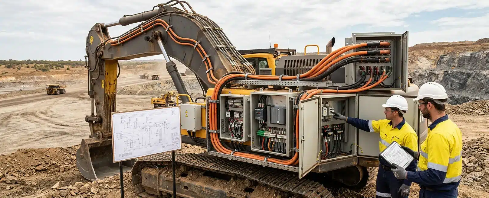
Electrified excavators put high-current DC power, battery mass and inverter heat onto a digging machine that already flexes, sheds dust and is maintained under time pressure. Power distribution, heat rejection, harness routing, vibration at the mounts and fitter access share the same boom, house, slew deck and service bays.
We design electrical architecture, high-voltage harness routing and safety circuits with that mechanical envelope, not after it is frozen. Name the loads, heat path, harness route, isolation method and charger connections against that excavator before the electrical design is signed. We are Engineered Installations Group, and that envelope check is the job we take before drawings go to manufacture.
Power Distribution and Safety Interfaces
The electrical heart of the machine is the network that feeds traction, hydraulics, charging and the circuits that must keep running when the high-voltage path is isolated. A single-line sketch will not catch a later clash with a hydraulic hose, a guard or a walkway.
High-Voltage Loads and Residual Circuits
Name every load that will sit on the high-voltage path, every load that must remain on the existing machine supply, and every point where those two worlds meet. For this class of plant, electrical system design is schematic and harness work for machinery, heavy vehicles and mobile equipment, not a generic industrial board layout.
Isolating the high-voltage supply for maintenance is not proof that the machine is free of stored energy. Battery packs and DC-link capacitors can remain charged until the isolation procedure for that machine is followed and verified.
Lights, controls and some hydraulic functions may still need the existing machine supply. If that boundary is not named, a fitter can meet a live circuit they did not expect.
Isolation, Interlocks and Distribution Heat
The schematic has to show isolation, emergency stops, interlocks and the communication network. It also has to leave the circuitry that still powers ordinary machine functions intact.
Safety circuits belong in the same set of drawings. We design redundant safety circuits such as emergency stops and interlocks against functional safety requirements as part of integrated system design.
Isolation method, lock-out points, connector access and the sequence a site electrician will follow need to be visible on those drawings. That is architecture and documentation. It does not mean an interlock will de-energise a live conductor before a person can touch it.
Current and conductor resistance still govern heat in the distribution path. Peak digging and charging currents make poor terminations, undersized sections and cramped junctions run hot.
Set cable size, connector choice, bundling and airflow against the duty the machine will see. Write that duty as a load case, meaning the currents and forces expected in service, rather than copying a diesel baseline.
Ask the battery and inverter suppliers for current limits, connector types and their isolation instructions. Use those as inputs, then set cable size and lock-out points on this excavator’s envelope.
Each lock-out point needs a location a site electrician can find with the machine parked. A load case that only exists in a calculation note will not protect a cramped junction that was never given space on the model.
Heat Rejection, Enclosures and Frame Loads
Heat on an electrified excavator is a packaging problem. Cells, inverters and high-current joints generate heat that has to leave the enclosure without cooking adjacent looms, hydraulic oil or a service space someone still has to enter.
Site Heat, Mass and Cooling Method
Australian mine sites are harsh on electronics. Ambient temperature, dust, radiant load from adjacent plants and blocked airflow belong on the input list. Cell operating limits still come from the battery supplier.
Keep enclosure geometry open until both the heat path and the structural path are named. A battery box can be electrically tidy and still be a poor mount if the frame, the added mass and the dynamic loads from digging and travel have not been assessed.
We use finite element analysis to look at stress, deflection, vibration and thermal behaviour, including structural integrity of battery enclosures and frame modifications under dynamic loads. That work needs realistic load cases, material data and a clear statement of what was assumed.
The cooling method follows those limits and the space that is actually available. Liquid plates, air paths or a hybrid arrangement may all be candidates once mass, radiator location, hose routing and service access sit on the same model.
Heat rejection needs a physical route that does not fight the harness, the mounts or the walkways. The enclosure and its brackets still have to survive the load cases used for the rest of the machine.
Missing heat or mount data forces clearances to be decided during build. Hold the electrical drawings until both paths are on the model.
Harness Routing, Vibration and Service Access
Excavators are high-vibration machines. Bucket impact, track travel and hydraulic pump oscillation fatigue terminations, chafe looms and loosen glands that looked adequate on a static layout. In a high-current path, a loose joint is a heat and fire problem, not only a nuisance fault.
Routing, Vibration and Manufacture
We use vibration data analysis to inform mounting and damping for sensitive electrical components when a repeating mechanical mode is actually measured. The loom still has to live with chassis flex.
We produce harness documentation with cut lists, material specifications and termination instructions. We use 3D routing so the loom is designed in the real envelope rather than as a stick diagram.
A stick diagram does not show the guard, the hose clamp or the slew bearing the loom has to miss. 3D routing puts the harness in that envelope so bend radius and abrasion can be judged before cable is cut.
Decide bend radius, clamp spacing, abrasion points, connector orientation and the slack needed for boom or house movement before the loom goes to manufacture. Industrial cable that is too stiff for mobile plants will try to take the strain at the crimp. Match the route and the supports to the machine.
Access and Electromagnetic Noise
Service access is part of the same decision. Isolation points, high-voltage connectors and diagnostic plugs need a path a competent person can reach with the machine in a realistic parked state.
If the mechanical model still hides those faces, 3D scanning of the as-built machine is a better input than guessing behind a cover.
Electromagnetic noise from power electronics can disturb radios and safety sensors. Our system work includes designing the power and communication network so it does not harm the circuitry that runs normal machine operations. Separation, shielding and earthing details belong to that machine and the site radios it must live with.
Documentation, Isolation and Functional Safety
A loom still needs a paper trail a mine can use. The drawings have to be usable for manufacture, installation, isolation and the certification path the project has already named.
Schematics, Isolation Instructions and As-Builts
Our electrical schematics are layouts for complete machinery systems and custom harnesses. They are drafted so assembly and troubleshooting are not exercises in decoding a sketch. Ambiguity in a high-voltage mobile system becomes a wrong termination or a missed isolator.
Identify the relevant Australian and international requirements in feasibility and write them into the compliance set. Functional safety for emergency controls is part of our integrated design scope. The wiring and performance of those circuits are proved against the requirements named for that project.
Label high-voltage routes and write isolation instructions that emergency and maintenance crews can actually use. Site sign-off of a fit-out is not the same as proving every legal duty the project may carry.
If the machine is a conversion, record what changed. As-built drawings, harness revisions and mount details have to match the machine that will be commissioned. Building a loom while the mechanical group is still moving a tank or a counterweight is how the wrong loom is cut.
Charging, Communication and Machine Interfaces
The excavator is only as usable as the charging and control connections it presents to the site. Machine-level electrical design has to know how the battery will be charged and which communication method the charger and the machine will share.
One Sheet for Charger and Controls
It also has to know which existing circuits must not be disturbed when that connection is live. The connector, the interlocks, the thermal limits the charger must respect and the physical space for the inlet belong on one list.
We close those connections through system integration. That work covers mechanical and structural mounting of electrical gear under shock and vibration, plus power and communication architecture, taking safety circuits from concept through detailed design, documentation and support to commissioning.
If the charger, the PLC, the hydraulic demand and the isolators are still owned by four different vendors with no single sheet, the electrical design is not ready.
Site power capacity, trailing cable, overhead infrastructure or a charge pad are mine inputs. The machine still has to declare what it will ask for and what it will refuse. Commissioning then checks that the built machine matches that declaration.
Workshop Build and Field Commissioning
How the first machine will be built is a constraint on the drawings, not an afterthought. Assembly of enclosures, inverters, harnesses and mounts is often better done where the machine can be held, measured and inspected through workshop installation.
Workshop, Field and Support Utes
We work from Forrestdale in Western Australia, with a Queensland presence at Paget, and field technicians mobilise when the work cannot be completed at the Perth facility. The practical question is whether the excavator can be brought to those facilities, or whether the first machine has to be finished where it already sits.
If the first machine has to be finished where it already sits, Australian light support utes become part of that commissioning plan. They carry chargers, spare looms and test sets around the parked excavator, and that extra payload changes load and handling on the ute. Plan braking and suspension upgrades on those utes before the electrical crew relies on them for isolation and functional checks in the field.
The drawings should say what will be built off-site, what can only be finished on the machine, and what commissioning will prove. We work alongside the fabrication team to resolve integration issues and support final system testing and commissioning.
Field installation, commissioning and maintenance remain available through on-site installation when the excavator cannot come into the bay. The fitter on the slew deck needs the same drawings used to cut the harness. Isolation and functional checks have to be written for the place the machine will actually be standing.
Workshop and site are sequential stages of the same build. A loom built to a 3D route still has to survive the first hours of digging. Mounts that passed a model still have to be inspected after transport.
The electrical design can be signed when one set of drawings shows how power, heat, the harness and the charger sit on this excavator, including isolation a parked machine can actually use. Commissioning then checks the built machine against that set.
To scope the work, send:
- machine identity and duty
- intended enclosure and mount locations
- load cases for digging, travel and charging
- circuits that must stay on the existing machine supply
- charger, interlock and safety list
- whether the first machine is a workshop or field build
Those inputs let us scope electrical design and system integration against the actual excavator rather than a generic heavy vehicle. To discuss the project, send that information.



Leave A Comment