
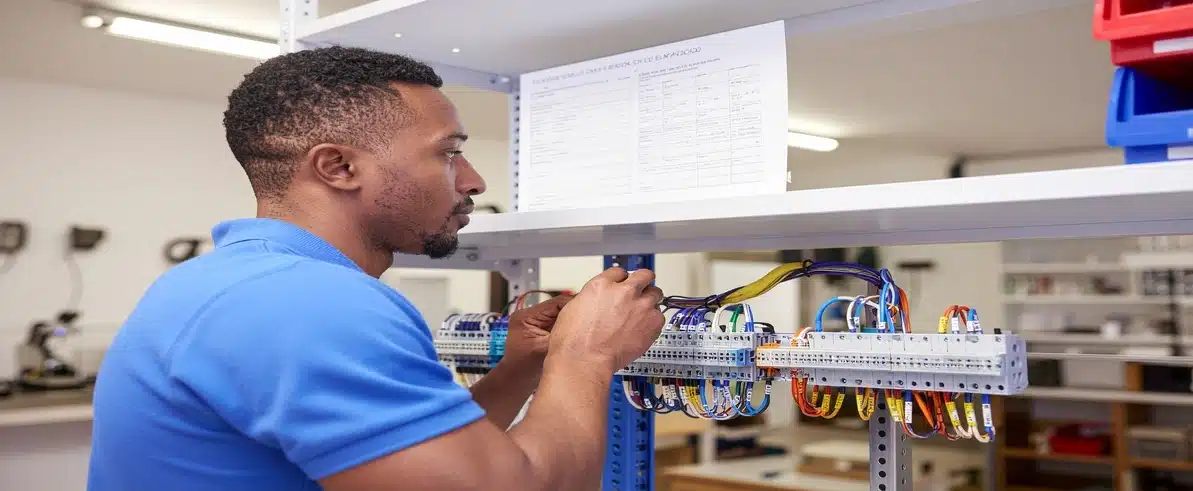
The speed and accuracy of electrical harness and system assembly is determined less by the skill of the assembler than by the quality of the documentation they are working from. An experienced technician working from a complete, accurate bill of materials and a set of well-structured termination instructions will consistently produce correct assemblies faster than an equally skilled technician working from incomplete or ambiguous documentation. In industrial electrical assembly for heavy vehicle and mining applications, where the cost of assembly errors is high and the stakes of in-service failure are serious, documentation quality is not a background consideration. It is a direct input to production efficiency and product reliability.
What Is a Bill of Materials in an Electrical Assembly Context?
A bill of materials (BOM) in an electrical assembly context is a structured document that lists every component required to build a defined electrical assembly, a harness, a control panel, a switchboard, or a complete vehicle electrical system, with sufficient identification and specification information to enable accurate procurement, kitting, and assembly. It is the primary interface between the engineering design and the supply chain, and between the supply chain and the assembly floor.
The distinction between a BOM and a general parts list is important. A parts list identifies what is needed. A BOM identifies what is needed, how many are needed per assembly, what their approved equivalent alternatives are, what specification or drawing they must conform to, and how they are organised within the assembly hierarchy. This additional structure is what makes a BOM a functional production document rather than a shopping list.
For complex multi-assembly systems, such as a complete vehicle electrical fitout that includes a main harness, several sub-harnesses, a control panel, and multiple bracket assemblies, the BOM is structured hierarchically, with a top-level assembly BOM that references the sub-assembly BOMs, each of which in turn references their component-level BOMs. This hierarchy allows each assembly to be procured, built, and inspected independently, while the top-level BOM provides a complete picture of the full system.
The Structure of an Effective BOM
Component Identification and Specification
The minimum identification information required in an electrical assembly BOM for each component includes the item number, the part description, the manufacturer’s part number, and the quantity required per assembly. Effective BOMs also include the approved manufacturer list, identifying which suppliers’ versions of a component are approved for use, and a reference to the specification or drawing that defines the component’s required performance.
Manufacturer part numbers are the critical identification element. Generic descriptions, “6mm² red cable” or “10A fuse”, are insufficient for production purposes because they do not uniquely identify a specific product and do not capture the specification details needed to verify that a substitute product is acceptable. A BOM that relies on generic descriptions will generate procurement queries, incoming inspection failures, and assembly disputes that slow production and introduce quality risk.
Approved equivalent information is equally important. Supply chain disruptions, product discontinuations, and regional availability constraints mean that the primary-choice component is not always available when it is needed. An effective BOM pre-qualifies alternatives so that procurement can substitute without an engineering query, and assembly can proceed without a production hold. This is particularly relevant for mining and heavy vehicle programmes where production continuity is tied directly to operational deployment schedules. EIG structures every BOM with this supply chain resilience in mind, pre-qualifying alternatives during the design stage rather than scrambling for them during production.
Quantity and Configuration Management
Quantities in a harness assembly BOM are expressed per assembly, the number of each component required to build one complete assembly. For components that are cut to length from stock material (wire, sleeving, conduit), the quantity must specify both the unit of measure and the cut length or total length per assembly, with appropriate allowance for waste and setup.
Configuration variants, assemblies that share a common design but differ in specific components or dimensions for different vehicle applications, are managed within the BOM through variant management structures that clearly identify which configuration each component applies to. Poor variant management in a BOM produces kitting errors that result in the wrong components being assembled into the wrong configuration, creating rework at best and in-service failures at worst.
Termination Instructions for Electrical Assemblies
What Termination Instructions Must Cover
Termination instructions are the assembly documentation that tells the technician exactly how each electrical connection in the assembly must be made. At minimum, they must specify the conductor preparation requirements (strip length, insulation removal method), the crimp tool to be used, the tool settings for the conductor size and contact type, the crimp inspection criteria, and any special requirements for connector assembly including contact insertion sequence, secondary lock activation, and sealant application.
The completeness of termination instructions directly determines assembly error rates and first-pass quality. Instructions that specify the crimp tool type without the tool setting leave the assembler to determine the correct setting independently, a process that introduces variability and error. Instructions that specify the inspection criteria without defining the acceptance and rejection limits leave the inspector to make subjective judgements that produce inconsistent outcomes.
Assembly documentation standards for industrial electrical applications require that termination instructions be maintained under document control and updated whenever the design or approved component list changes. Instructions that are not kept current with the design produce assemblies that conform to a superseded standard, creating potential compliance and quality issues. The electrical engineering solutions service at EIG produces and maintains termination instruction packages as a formal engineering deliverable, not an afterthought, ensuring they remain accurate and current across the full production lifecycle.
Termination Instruction Formats and Standards
The standard format for termination instructions in industrial electrical assembly is governed by IPC/WHMA-A-620 (Requirements and Acceptance for Cable and Wire Harness Assemblies), which defines both the technical acceptance criteria for terminations and the documentation format used to specify them. Working within this standard ensures that termination instructions produced by one organisation can be understood and applied by any assembler trained to the IPC/WHMA-A-620 standard, which is particularly important for programmes where assembly is subcontracted or where the assembly facility changes over the product’s life.
Component specification sheets, when included with or referenced from termination instructions, provide the assembler with the detailed information about each component’s design and performance requirements that cannot practically be included in the instruction itself. The specification sheet for a crimp contact, for example, will include the conductor size range, the required crimp cross-section dimensions, and the pull-out force requirement for an acceptable crimp, all of which inform the termination instruction and acceptance criteria.
Assembly Documentation Standards for Heavy Vehicle Applications
Heavy vehicle and industrial electrical assemblies are subject to a combination of documentation standards that govern drawing format, revision control, document release, and records management. In Australia, the primary applicable standards include AS/NZS 1580 for drawing documentation and the various AS/NZS and IEC standards that govern specific electrical installation and assembly requirements.
Beyond these formal standards, major mine operators and OEM customers typically impose additional documentation requirements that must be reflected in the assembly documentation package. These requirements may specify document numbering conventions, revision management processes, approval workflows, and records retention periods. Assembly documentation that does not meet these customer-specific requirements may be rejected during the supply qualification process, delaying programme commencement.
BOM specification development must account for these customer documentation requirements from the outset, ensuring that the documentation structure and format adopted during the design phase are compatible with the customer’s requirements for production and ongoing supply.
BOM Specification Development: From Design to Production
The bill of materials that supports production is not the same document that is produced during the design phase. A design-stage BOM captures the intent of the design, the components that are expected to be used, in the approximate quantities required, but it has not yet been validated against actual production experience and may contain components that are unavailable, incorrectly specified, or impractical to assemble.
BOM specification development for production involves a systematic validation process that begins with the first-article build. During first-article production, every component in the design BOM is procured and used to build a complete assembly, and any issues with component availability, specification accuracy, or assembly practicality are identified and resolved. The BOM is updated to reflect the validated component selections and any adjustments to quantities or specifications made during first-article.
Following first-article validation, the BOM is formally released under document control and communicated to the supply chain. Approved supplier qualification records are linked to the BOM to define which supplier’s version of each component is approved, and the BOM is placed under change management to ensure that subsequent modifications are assessed for impact before being implemented in production. For programmes that combine BOM development with harness manufacture and vehicle installation, the workshop installation services at EIG’s Perth facility provide the controlled environment needed to carry out first-article builds and production runs to a consistent standard.
Component Specification Sheets and Their Role in Assembly
Component specification sheets provide the detailed technical information about individual components that cannot be captured in the BOM entry itself. For electrical components, this includes electrical ratings, environmental ratings, dimensional and weight data, installation and handling requirements, and quality and inspection acceptance criteria.
In the context of harness and electrical system assembly, specification sheets serve several roles. They provide the technical basis for incoming inspection, defining what characteristics must be verified when components are received from the supply chain. They provide the technical reference for assembly quality control, defining what a correct assembly looks like. And they provide the technical basis for field service, defining what replacement components must conform to when the original is no longer available.
Specification sheets must be kept current with the approved component list. Where a substitute component is approved during the production lifecycle, the specification sheet must be updated to reflect the substitute’s characteristics, ensuring that incoming inspection and assembly quality control remain calibrated to the actual components being used.
How Documentation Quality Affects Assembly Speed
The relationship between documentation quality and assembly speed is direct and measurable. Assembly queries, occasions when a technician must stop work to seek clarification of an ambiguous instruction, are among the most common causes of assembly throughput loss. Each query consumes the time of both the assembler and the technical authority who must respond to it, and in a production environment where multiple assemblies are being built simultaneously, the cumulative impact of frequent queries is significant.
Rework caused by assembly errors that trace back to documentation ambiguity or inaccuracy represents a more substantial throughput loss. Rework at the assembly stage consumes materials, labour, and inspection time, and where rework is required on a completed and tested assembly, it may require re-testing that further extends the production cycle time.
Engineered Installations Group treats BOM and termination documentation as engineering deliverables with the same importance as schematic drawings and harness assembly documentation. The investment in producing complete, accurate, and well-structured assembly documentation at the design stage is recovered many times over in reduced query rates, lower rework rates, and faster assembly throughput across the production run. For fleet and OEM programmes where the on-site installation support team is completing builds in the field, documentation quality is even more critical, field technicians cannot walk across the floor to query a designer, so the instructions must be unambiguous from the outset.
EIG’s Approach to BOM and Termination Documentation
EIG’s approach to BOM and termination documentation treats these documents as the foundation of a reliable, repeatable assembly process, not as administrative outputs produced after the real work is done. Every BOM is developed with production use in mind: structured for the assembly floor, populated with manufacturer part numbers and approved equivalents, and formatted to align with the documentation requirements of the programmes it supports.
Termination instruction packages are produced in parallel with the schematic and harness design, ensuring that the instructions are aligned with the actual components and tooling specified in the design rather than being reverse-engineered from a finished assembly. This integrated approach to documentation development is what produces instruction sets that can be followed accurately, first time, without queries or interpretation.
Conclusion
Bill of materials and termination instructions are the documents that translate an electrical system design into a reproducible, inspectable manufacturing process. When they are complete, accurate, and structured to the appropriate standards, they enable fast, consistent, first-pass-correct assembly. When they are not, they generate queries, rework, and delays that compound across every assembly in a production run. In heavy vehicle and industrial electrical applications, where assembly quality has direct safety implications and production delays have real operational costs, the quality of these documents is an engineering priority, not an administrative one. To discuss BOM and termination documentation development for your electrical assembly programme, call +61 (08) 9419 7318 to speak with the EIG team.



Leave A Comment