
Mining equipment operates under some of the harshest conditions imaginable. Haul trucks carry hundreds of tonnes across uneven terrain. Excavators swing massive loads through repetitive cycles. Drill rigs generate extreme vibration and impact forces. When a structural component fails in these applications, the consequences extend far beyond repair costs – they include production downtime, safety incidents, and potential fatalities.
Finite element analysis provides the engineering rigour required to predict how these structures will behave before they’re built. Rather than relying on oversized components and safety margins based on guesswork, FEA uses computational modelling to simulate exactly where stress concentrations occur, how materials will deform under load, and whether a design will survive its intended service life.
Why Heavy Mining Equipment Demands Advanced Engineering Analysis
The Operational Gap That Standard Design Methods Cannot Close
The operational environment for mining equipment creates loading scenarios that standard design approaches struggle to address. A haul truck frame doesn’t just support a static payload – it experiences dynamic loads from acceleration, braking, cornering, and traversing rough haul roads. An excavator boom doesn’t simply lift a bucket – it undergoes cyclical loading that can lead to fatigue failure after millions of cycles.
Traditional design methods often compensate for uncertainty by adding material, which increases weight, fuel consumption, and component cost. Structural stress simulation allows engineers to identify precisely where material is needed and where it can be removed without compromising safety. This optimisation becomes particularly valuable in heavy mining equipment design, where every kilogram of unnecessary weight translates to reduced payload capacity or increased fuel consumption across the equipment’s decades-long service life.
Regulatory Drivers and Safety Documentation
Regulatory requirements in the mining industry have driven the adoption of rigorous engineering analysis. Equipment operating in underground mines or autonomous mining operations must meet stringent safety standards that require documented structural integrity verification. FEA provides the analytical evidence needed to demonstrate compliance and support engineering sign-off.
What Finite Element Analysis Actually Does
At its core, finite element analysis is a computational method that breaks down complex structures into thousands or millions of smaller elements. Each element is assigned material properties, and the software calculates how forces distribute through the structure based on fundamental physics principles – stress-strain relationships, equilibrium equations, and compatibility conditions.
Breaking Down Complex Structures into Manageable Elements
The first step in any FEA study involves converting a CAD model into a mesh of finite elements. For a haul truck chassis, this might mean dividing the frame rails, cross members, and mounting points into hundreds of thousands of tetrahedral or hexahedral elements. The mesh density determines analysis accuracy – finer meshes capture stress gradients more precisely but require greater computational resources.
Element selection depends on the geometry and loading conditions. Shell elements work well for thin-walled structures like truck bodies. Solid elements suit thick components such as excavator boom sections. Beam elements efficiently model frame members where length significantly exceeds cross-sectional dimensions.
The mesh generation process requires engineering judgement. Areas expecting high stress concentrations – such as weld toes, bolt holes, or sharp corners – need refined meshes to capture peak stresses accurately. Regions with relatively uniform stress distributions can use coarser meshes without sacrificing result quality.
Simulating Structural Behaviour Under Operating Loads
Once the mesh is established, the analyst applies boundary conditions and loads that represent how the equipment actually operates. For a mining excavator, this might include the weight of a fully loaded bucket, the hydraulic cylinder forces during digging, the inertial loads from swing motion, and the support reactions at the undercarriage.
Load cases should capture the most severe operating scenarios. A mechanical load analysis for a haul truck might evaluate maximum payload on a 15% grade, emergency braking with full load, and cornering at maximum speed. Each scenario produces a different stress distribution, and the design must satisfy safety requirements for all cases.
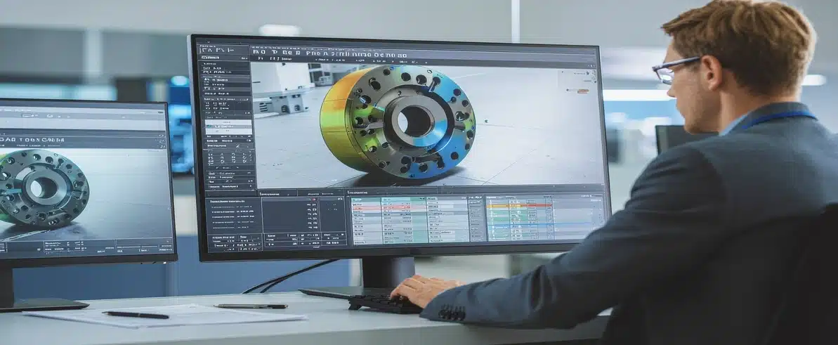
The FEA software solves thousands or millions of simultaneous equations to calculate displacements at every node in the mesh. From these displacements, it derives strains and stresses throughout the structure. The output includes stress contour plots showing where peak stresses occur, deformation plots revealing how the structure deflects, and safety factor calculations comparing predicted stresses to material allowables.
The FEA Process for Heavy Mining Equipment Design
Conducting structural integrity verification for mining equipment follows a systematic workflow that ensures reliable results. The process begins with defining the analysis objectives – whether that’s validating a new design, investigating a field failure, or optimising an existing component for weight reduction.
CAD Model Preparation and Material Definition
CAD model preparation is often the most time-consuming phase. Production models contain features irrelevant to structural analysis – small fillets, bolt threads, cosmetic details – that must be removed or simplified. The analyst retains features that significantly affect stress distribution while eliminating details that would unnecessarily complicate the mesh without improving accuracy.
Material property definition requires careful attention for mining applications. High-strength steel grades used in excavator structures have different stress-strain curves than mild steel in truck bodies. Weld metal properties differ from base metal. Temperature effects may need consideration for equipment operating in extreme heat or cold. The analysis is only as accurate as the material data it uses.
Load Case Development and Fatigue Considerations
Load case development draws on operational data, manufacturer specifications, and industry standards. For load-bearing component analysis, this means understanding actual duty cycles – not just peak loads but the frequency and duration of various loading conditions. Fatigue analysis requires load histories that capture the cumulative damage from millions of cycles.
Interpreting Results With Engineering Expertise
Interpreting results demands engineering expertise. A stress contour plot might show a local peak at a sharp corner, but is that peak a genuine concern or an artefact of the geometry idealisation? Does the predicted deformation affect equipment function? Are the safety factors adequate given uncertainties in loads, material properties, and analysis assumptions?
These are judgement calls that distinguish meaningful analysis from misleading output.
Where FEA Delivers the Greatest Value in Mining Applications
Excavator Booms, Sticks, and Structural Optimisation
Excavator booms and sticks experience complex loading from bucket digging forces, hydraulic cylinder reactions, and dynamic effects during swing and hoist. Structural stress simulation reveals stress distributions that simple hand calculations cannot predict, allowing engineers to optimise cross-sections and reduce weight without compromising strength.
Haul Truck Chassis and Fatigue-Critical Inspection Planning
Haul truck chassis frames must support enormous payloads while maintaining durability through millions of kilometres of operation. Load-bearing component analysis identifies fatigue-critical locations where crack initiation is most likely, informing inspection intervals and maintenance procedures. It also guides reinforcement strategies when uprating trucks for higher payload capacities.
Weld Integrity and Auxiliary Attachment Points
Weld integrity is particularly critical in fabricated mining structures. FEA assesses stress concentration factors at weld toes, evaluates the effects of weld distortion on structural behaviour, and determines whether partial-penetration welds provide adequate strength. This analysis directly supports welding procedure development and quality assurance.
Attachment points for auxiliary equipment – such as collision avoidance system mounting brackets, lighting towers, or hydraulic tank supports – introduce local loads that the original structure may not have been designed to accommodate. Mechanical load analysis verifies that these modifications don’t create unacceptable stress concentrations or fatigue risks.
How FEA Reduces Development Costs and Time
Compressing Design Iteration Cycles
The traditional approach to validating heavy equipment designs relies heavily on physical prototype testing. Build a component, install it on a machine, operate it until it fails or proves durable, then iterate based on results. This process is expensive and slow, often requiring months between design iterations.
Finite element analysis compresses this cycle significantly. Engineers can evaluate dozens of design variations in the time it would take to build and test a single prototype. They identify problems early, when changes require updating a CAD file rather than scrapping fabricated components. The analysis guides prototype testing by predicting where to place strain gauges and what loads to apply for meaningful validation.
Material Optimisation and Long-Term Cost Benefits
Material optimisation represents another significant cost benefit. FEA reveals where high-strength steel is genuinely necessary and where standard grades suffice. It identifies opportunities to remove material from low-stress regions, reducing weight and cost simultaneously. For large mining equipment, even modest weight reductions can deliver meaningful fuel savings over the equipment’s service life.
Early-Stage Failure Identification
Early-stage failure identification prevents costly field issues. Discovering a fatigue problem through analysis costs engineering time. Discovering it through premature field failures costs downtime, warranty claims, reputation damage, and potentially safety incidents. The investment in thorough structural integrity verification during design pays dividends throughout the equipment’s operational life.
Combining FEA With Other Engineering Services
Vibration Data Analysis and Measured Load Inputs
Vibration data analysis provides operational data that informs FEA load cases and validates analysis predictions. Measured vibration levels during equipment operation reveal actual dynamic loads, which may differ from theoretical calculations. This measured data improves analysis accuracy and ensures conservative design margins.
3D Modelling for Legacy Equipment and Field Modifications
3D modelling services support FEA when CAD models don’t exist for legacy equipment or field modifications. Laser scanning captures as-built geometry, which can be converted to solid models suitable for analysis. This capability is particularly valuable when investigating failures in older equipment or validating field modifications that weren’t formally engineered.
System Design and Standardised Fleet Modifications
System design integration ensures that structural analysis considers the complete operating environment. A bracket designed to support a battery management system must account for not just the static weight but also the vibration environment, thermal expansion, and electrical isolation requirements. FEA validates that the structural design satisfies all these constraints simultaneously.
For organisations operating mixed fleets, the combination of finite element analysis with comprehensive engineering support enables standardised modification procedures. Once a particular fitout has been validated through FEA, it can be replicated across multiple vehicles with confidence. This approach is common for customised kit solutions where structural modifications must maintain vehicle safety ratings and regulatory compliance.
Conclusion
The value of finite element analysis depends entirely on how it’s implemented. Sophisticated software tools are widely available, but generating meaningful results requires engineering judgement developed through experience. An analyst must understand not just how to operate the software but also the underlying mechanics principles, the behaviour of mining equipment structures, and the practical constraints of fabrication and operation.
The mining industry’s operational demands leave no room for structural failures. Equipment must perform reliably in conditions that would destroy lesser machines, and it must do so for decades. Finite element analysis provides the engineering foundation that makes this reliability possible, transforming heavy mining equipment design from an exercise in conservatism into a science based on rigorous analysis and optimisation.
Engineered Installations Group applies structural stress simulation to validate modifications ranging from simple mounting brackets to complete vehicle reconfigurations. This analytical rigour ensures that field installations maintain the structural integrity and safety margins that mining operations demand. For projects requiring detailed structural integrity verification or mechanical load analysis, call +61 (08) 9419 7318 to discuss your engineering requirements.



Leave A Comment