
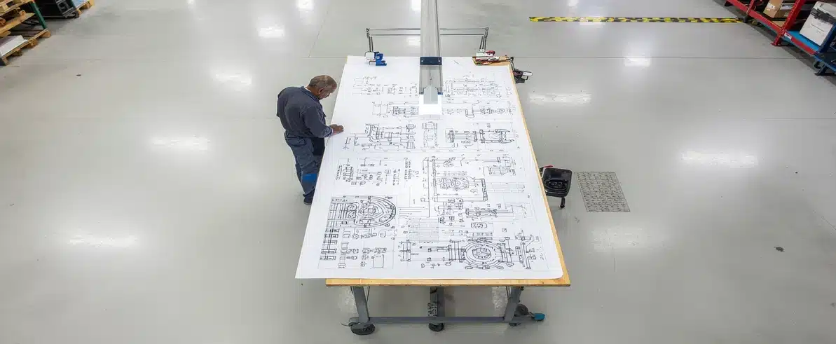
Every electrical system installed on a heavy vehicle begins as a drawing. The quality of that drawing, the rigour with which it captures the system’s architecture, the accuracy of its component references, and the clarity of its circuit logic, determines how well the system can be built, commissioned, maintained, and repaired across its service life. In the context of mining and heavy transport vehicles, where electrical systems support safety-critical functions and operate in demanding conditions for years at a time, the standard of the initial schematic is not a documentation formality. It is the engineering foundation on which everything else rests.
What Are Electrical Schematics and Why Do They Matter?
Electrical schematics are technical drawings that represent the logical structure of an electrical circuit or system. They show how components are connected, how circuits are protected, how control signals flow, and how the system interacts with other vehicle systems. Unlike a physical wiring diagram that shows where wires are routed in three-dimensional space, a schematic is an abstraction that captures the functional logic of the system independent of physical layout.
This distinction matters because the schematic is the primary tool used by engineers to design and verify a system before it is built. A wiring diagram can show that a cable runs from point A to point B; a schematic shows why, under what conditions the circuit is active, what protection it has, and how it interfaces with adjacent systems. For complex heavy vehicle installations with multiple interacting systems, the schematic is the only document that captures the full picture of how the electrical system behaves.
Industrial electrical design for heavy vehicles differs from consumer automotive design in one critical respect: complexity. A standard passenger vehicle has dozens of circuits managed by a central body control module. A fully fitted-out mine-site service truck may have hundreds of circuits spanning OEM systems, safety fitout, communications, hydraulic controls, auxiliary power, and monitoring systems. Without engineering-grade electrical schematics, the interactions between these systems cannot be understood, verified, or reliably maintained.
Engineering-Grade vs Informal Wiring Documentation
The distinction between engineering-grade schematic design and informal wiring documentation is the difference between a document that can be used to build, verify, and maintain a system, and one that can only be used to understand what was done at a point in time. Informal documentation, hand-drawn sketches, incomplete circuit descriptions, photographs of finished wiring, captures the result of a build without capturing the design intent, the circuit protection logic, or the component specifications needed to replicate or modify it.
The risks of working from informal or incomplete wiring records are substantial. When a fault occurs in a system with adequate schematic documentation, an experienced technician can trace the fault systematically using the schematic as a reference, identify the affected circuit, and test components in a logical sequence. When the same fault occurs in a system with informal documentation, the technician must first reverse-engineer the wiring to understand what was installed, then attempt to identify the fault without a reliable reference, a process that multiplies diagnostic time and increases the risk of incorrect diagnosis.
Across a fleet, the compounding effect of poor documentation is significant. Each vehicle that enters service without adequate electrical schematics accumulates a maintenance liability that grows over time as technicians make informal repairs and modifications not captured in any record. EIG produces and maintains as-built schematics for every system it designs and installs, ensuring that the documentation delivered with each vehicle accurately reflects the installed system from day one.
Electrical Schematic Design Standards for Heavy Vehicles
Electrical schematic design for heavy vehicles in industrial applications is governed by a combination of Australian standards, international standards, and industry-specific requirements. AS/NZS 3000 (wiring rules) provides the foundational requirements for electrical installation practice, while AS/NZS 1580 and related standards govern drawing conventions and documentation practices for electrical drawings.
Wiring diagram standards specify the drawing symbols, annotation conventions, and document structure that must be used in compliant electrical documentation. Consistent use of these standards ensures that schematics produced by one organisation can be read and interpreted by engineers and technicians from another, which is particularly important in the mining sector where vehicles and equipment pass between multiple contractors, owners, and maintenance providers.
Component references in engineering-grade schematics must be unique, consistent with the components actually installed, and linked to a parts list or bill of materials that captures product specifications. Schematics that use generic component symbols without specific references are technically incomplete and cannot support accurate fault diagnosis or maintenance planning.
Heavy Vehicle Wiring Documentation
What a Complete Documentation Set Includes
A complete heavy vehicle wiring documentation package extends beyond the schematic itself. The full set of documents required to support design, installation, maintenance, and compliance verification typically includes the circuit schematic, a wiring harness layout drawing showing the physical routing of main cable runs, a connection schedule listing every termination point with its cable reference, component and conductor specifications, a bill of materials, and a completed installation and test record.
Each document type serves a different purpose. The schematic is used for design verification, fault diagnosis, and system modification planning. The harness layout drawing supports installation and is used when physical cable routing needs to be referenced during maintenance. The connection schedule is used during installation to verify that every termination has been made correctly, and during fault diagnosis to identify and test specific connection points.
The quality of the schematic determines the quality of all downstream documents. A schematic that is inaccurate, incomplete, or uses non-standard symbols and references produces a bill of materials that cannot be reliably used for procurement, a connection schedule that introduces errors during installation, and maintenance records that do not accurately reflect the installed system. The electrical engineering solutions capability at EIG covers the complete documentation set, from initial schematic through to as-built records, ensuring every deliverable is consistent and fit for purpose.
How Wiring Diagram Standards Support Compliance
Standardised wiring documentation is a direct enabler of minesite access approval. Mine operators assessing a vehicle for site access need to understand what has been installed, how it has been wired, and whether it meets the relevant standards. Documentation produced to a recognisable standard, using standard symbols, consistent references, and a logical document structure, can be reviewed efficiently by site engineers and safety officers.
Vehicle modification certification also depends on schematic quality. When a structural or electrical modification is formally certified, the certifying engineer’s assessment is based on the documentation provided. Incomplete or non-standard schematics slow this process and may prevent certification until the documentation is brought to the required standard. As-built schematics must be updated whenever modifications are made to the installed system, maintaining an accurate record of the system as it actually exists.
Industrial Electrical Design Principles for Vehicle Applications
Industrial electrical design principles applied to heavy vehicle systems address the specific challenges of complex, multi-circuit systems operating in demanding environments. The core principles include load management, circuit protection, earthing architecture, and electromagnetic interference management.
Load management in heavy vehicle electrical design involves calculating the total electrical demand of all installed systems and verifying that the vehicle’s generating and storage capacity can sustain this demand under all operating conditions. Correctly sized cables, fuses, and circuit breakers protect the system from faults without unnecessarily limiting its capability.
Earthing architecture is a frequently underestimated design element in complex vehicle electrical systems. Poor earthing is responsible for a disproportionate share of intermittent electrical faults in heavy vehicles, because the return path for electrical current is shared across multiple systems and a poor connection in the earth network affects every system downstream of it. Engineering-grade schematics explicitly document the earthing architecture, including the location and rating of earth connection points and the routing of earth conductors.
Electromagnetic interference management is relevant wherever sensitive electronic systems, telematics, fleet management terminals, proximity detection equipment, operate in close proximity to high-current switching circuits. Good schematic design documents the interference management measures implemented, including shielding, filtering, and physical separation of signal and power wiring. For integrated fitout programmes that combine electrical system design with physical installation, the workshop installation services at EIG’s Perth facility provide the controlled environment needed to implement and verify these design measures correctly.
Schematics as a Fault Diagnosis Tool
The practical value of accurate electrical schematics is most clearly demonstrated when a fault occurs. With an accurate schematic, an experienced technician can identify the affected circuit from the fault symptoms, isolate the circuit from adjacent systems, and test components in a systematic sequence that moves from the most likely failure points outward. This process typically resolves most electrical faults in a fraction of the time required when working without documentation.
Without adequate schematics, the same technician must first establish what the circuit is supposed to do and how it is wired, then attempt diagnosis on a system they do not fully understand. This process is slower, more likely to result in incorrect diagnosis, and more likely to result in additional damage from incorrect testing or repair attempts.
In a remote mining environment where vehicles are many hours from the nearest qualified electrical technician and every hour of downtime has a measurable cost, the difference between a documented and undocumented system is directly visible in maintenance budgets and operational continuity.
Schematics in the Design-Build-Commission Cycle
Engineering-grade schematics function as the master reference document throughout the full design, build, and commissioning cycle of a heavy vehicle electrical system. During design, the schematic is used to verify that all circuit requirements have been addressed and that the system architecture is sound. During the build phase, technicians reference the schematic and connection schedule to verify each wiring and termination step. During commissioning, the schematic is used to plan and execute the testing sequence, verifying that each circuit functions correctly before the vehicle is released.
After commissioning, the as-built schematic becomes the primary maintenance reference for the vehicle’s service life. Any modifications made during service must be captured in an updated schematic to preserve the accuracy of the record. Where integrated system design documentation is needed alongside physical installation, the system design services available through EIG support clients who require a complete design and documentation solution before engaging installation resources.
EIG’s Electrical Schematic Design Capability
Engineered Installations Group produces engineering-grade electrical schematics for heavy vehicle systems as a standard part of every fitout project. Schematics are developed using professional CAD tools to industry drawing standards, and are produced at the design stage, before installation begins, ensuring that the installation team has a clear reference and that the completed system can be verified against the design intent.
The schematic documentation produced by EIG is structured to meet the requirements of major Australian mine operators for vehicle access approval, and is produced at a standard that supports formal engineering certification where required. For procurement managers evaluating EIG’s technical capability, further detail on qualifications and project experience is available in the capability statement.
Conclusion
Engineering-grade electrical schematics are the document from which every reliable heavy vehicle electrical system flows. They capture the design intent, define the installation standard, enable systematic fault diagnosis, and provide the compliance evidence needed for minesite access and certification. In an industry where electrical system failures have direct safety and financial consequences, the investment in proper schematic documentation at the outset is among the highest-return engineering decisions a fleet operator can make. To discuss electrical schematic design for your heavy vehicle systems, call +61 (08) 9419 7318 to speak with the EIG team.



Leave A Comment