
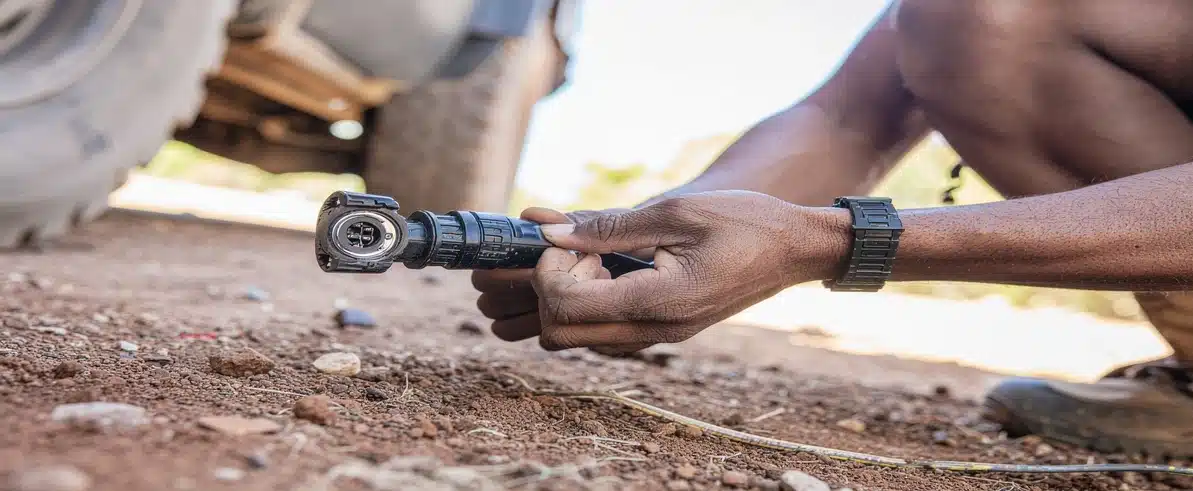
Electrical faults are among the most common causes of unplanned downtime in mining and heavy transport fleets. They are difficult to diagnose, often intermittent in their presentation, and frequently located at points in the vehicle that are difficult to access for inspection and repair. In the majority of cases, the root cause of these faults traces back not to component failure in isolation, but to design and installation decisions made during the vehicle’s initial fitout, decisions about conductor sizing, connector selection, harness routing, and termination method that determine whether the harness will perform reliably across its service life or generate a steady stream of in-service faults. Understanding how harness design directly influences field failure rates is the starting point for addressing them systematically.
The Cost of Harness-Related Field Failures
The direct cost of a harness-related field failure includes the diagnostic time required to identify the fault, the cost of parts and labour to repair it, and the downtime of the vehicle during this process. In a mine or transport environment where vehicles are essential to production continuity, downtime costs quickly exceed the value of the failed component, particularly when the fault requires specialist electrical expertise that may not be immediately available on site.
Indirect costs compound this figure. A vehicle that fails mid-shift must be recovered from its operating location, creating secondary plant movements and potential safety exposures. Diagnostic time on a poorly documented system can extend over multiple shifts as technicians work to understand the wiring architecture before they can address the fault. When the same fault type recurs across multiple vehicles in a fleet, the cumulative cost quickly becomes a significant operational liability.
Harness failure prevention is therefore not purely a technical consideration. It is a fleet management and financial performance issue. Fleets that invest in properly designed, well-manufactured harnesses with adequate documentation experience lower fault rates, shorter diagnostic times, and reduced total maintenance costs over the service life of their vehicles.
Common Harness Failure Modes in Mining Environments
Abrasion and Mechanical Damage
Abrasion is the most common mechanical failure mode for wiring harnesses in mining vehicle applications. Harnesses that are not correctly protected or routed will develop insulation damage over time as they rub against chassis components, body panels, and other cables. In a mining environment, where vibration is sustained and road surfaces are irregular, this process is accelerated relative to road transport applications.
Common chafing points on mine-site vehicles include harness runs adjacent to body mounting brackets, harnesses that pass through unsupported holes in chassis members without grommets, and harnesses that share routing paths with hydraulic hoses or mechanical cables that move relative to the chassis during operation. At each of these points, inadequate protection will produce insulation damage that progresses from surface abrasion to conductor exposure, resulting in intermittent or permanent short circuits.
Field wiring reliability depends on harness routing design that anticipates these failure points and provides appropriate mechanical protection at each of them. This requires the harness designer to understand the specific vehicle platform’s geometry, the locations of components that create chafing risk, and the types of relative movement that occur between different vehicle subsystems during operation. EIG applies this vehicle-specific knowledge at the design stage, so protection decisions are made on the drawing before a cable is cut, not discovered during a fault investigation.
Connector and Termination Failures
Connector failures are responsible for a significant proportion of intermittent electrical faults in mining vehicle harnesses. Moisture ingress through inadequately sealed connectors causes contact corrosion that increases contact resistance progressively over time, eventually producing voltage drop or complete circuit failure. Vibration-induced fretting wear on connector contacts produces a similar result through a different mechanism, as the microscopic relative movement between contact surfaces removes the oxide-free metal layer that provides reliable electrical contact.
Termination quality control at the manufacturing stage is the primary defence against these failure modes. Crimped terminations that are made with correctly calibrated tooling, inspected against defined acceptance criteria, and assembled into properly sealed connectors will resist moisture ingress, contact corrosion, and vibration-induced fretting for the service life of the harness. Those made with incorrect tooling or inadequate process controls will fail prematurely, often after a period of apparently satisfactory operation that masks the latent fault.
Connector selection must match the severity of the operating environment. Connectors used on mine-site vehicles must provide adequate IP ratings for their locations, positive locking mechanisms to resist vibration-induced unmating, and contact materials and plating that are appropriate for the chemical environment.
Thermal and Chemical Degradation
Thermal and chemical degradation of harness insulation is a failure mode that develops slowly and is often not detected until the insulation has already suffered significant damage. In mining vehicle applications, harnesses may be exposed to sustained high temperatures near exhaust systems, turbochargers, and hydraulic components; to chemical exposure from hydraulic fluid, fuel, cleaning solvents, and battery acid; and to UV radiation from extended outdoor exposure.
Insulation types that are adequate for standard automotive applications may not provide the necessary resistance to these combined exposures. PVC insulation, which is the most common conductor insulation in general automotive wiring, softens progressively at elevated temperatures and becomes brittle when exposed to certain chemicals, eventually cracking and exposing the conductor. Cross-linked polyethylene (XLPE) and thermoplastic elastomer (TPE) insulations provide significantly better thermal and chemical resistance for high-demand applications.
How EIG’s Harness Design Addresses Failure Modes
EIG’s approach to harness design treats the known failure modes of mining vehicle harnesses as design inputs rather than maintenance outcomes. Every harness design begins with an assessment of the operating environment specific to the vehicle platform and application, identifying the locations and mechanisms through which failure is most likely to occur.
Routing design is developed to minimise exposure to abrasion and chafing risks, with mechanical protection specified for locations where avoidance is not possible. Connector selection is based on IP rating, vibration resistance, and chemical compatibility requirements appropriate to each connector location. Conductor and insulation specifications are determined by load calculations and thermal environment assessments, not by generic standards.
This systematic approach to harness failure prevention produces designs that perform reliably across extended service periods, with significantly lower in-service fault rates than harnesses designed to minimum automotive standards or adapted from off-the-shelf products. For fleet programmes involving multiple vehicles, the workshop installation services at EIG’s Perth facility enable consistent harness builds across the full fleet, so that every vehicle enters service with the same level of protection designed in from the start.
Termination Quality Control in Harness Manufacturing
The quality of every termination in a harness is a direct determinant of the harness’s field reliability. EIG’s manufacturing quality control for harness production covers the full range of termination and assembly operations, from conductor preparation and crimp setting selection through to final harness electrical testing.
Crimping operations are performed with calibrated tooling set to the correct parameters for the conductor size and contact type. Crimp cross-sections are inspected visually and, where required, by pull-test and cross-section measurement against the acceptance criteria specified in IPC/WHMA-A-620. Connector assemblies are inspected for correct pin installation, positive secondary lock engagement, and sealing system integrity before being incorporated into the finished harness.
Final harness testing includes continuity verification of every circuit, insulation resistance testing, and physical inspection of the completed assembly against the harness drawing. Any harness that does not meet the acceptance criteria is rejected and repaired or scrapped before leaving the manufacturing area.
Field Wiring Reliability: Installation and Post-Installation Practices
Design and manufacturing quality are necessary but not sufficient conditions for field wiring reliability. A correctly designed and manufactured harness that is poorly installed will develop the same failure modes as a poorly designed harness, because installation quality determines whether the design intent is preserved in the finished vehicle.
Routing compliance during installation requires the installation technician to follow the planned routing path, install support clips at the specified intervals, and apply protective grommets and fittings at all bulkhead penetrations. Deviations from the planned routing that create new chafing risks or remove planned mechanical protection negate the design work that identified and addressed those risks.
Engineered Installations Group applies the same quality standards to harness installation as to manufacturing, with staged inspection checkpoints during installation and a post-installation verification that confirms routing compliance, support spacing, connection correctness, and system function before the vehicle is released. The on-site installation support capability extends this quality standard to remote site installations where workshop conditions are not available.
Preventive Maintenance Servicing for Harness Systems
Even correctly designed, manufactured, and installed harnesses require periodic inspection to sustain their performance across an extended service life. Mine-site operating conditions that subject harnesses to sustained vibration, temperature cycling, and contamination will progressively stress even the most robust designs, and early identification of developing issues avoids the more serious and costly consequences of in-service failure.
Preventive maintenance servicing for harness systems covers visual inspection of harness routing and mechanical protection integrity, connector condition assessment including sealing system inspection and contact resistance measurement, and thermal imaging of high-current connection points to identify developing high-resistance joints before they progress to failure. These inspections can be structured to align with existing vehicle service intervals, minimising the additional logistical burden on fleet management teams.
Harness Failure Prevention as a Fleet Management Strategy
At a fleet level, systematic attention to harness design quality and maintenance translates into measurable improvements in fleet availability, maintenance cost, and safety performance. Fleets where all vehicles are built to a consistent harness design standard, with complete documentation, benefit from shorter diagnostic times when faults do occur, because technicians can reference the same documentation across all vehicles rather than reverse-engineering each one individually.
Standardisation of connector types and harness architecture across a fleet also simplifies parts management and reduces the inventory required to support field repairs. When a connector or harness section needs to be replaced, a standardised fleet configuration means the replacement part is known and stocked, rather than requiring a custom solution to be sourced. For procurement managers evaluating harness design capability, the capability statement from EIG provides a detailed overview of the team’s qualifications, manufacturing processes, and project experience across mining and transport fleet programmes.
Conclusion
Field failures in mining and transport equipment harnesses are not random events. They are the predictable consequences of design decisions that fail to account for the operating environment, manufacturing practices that produce poor-quality terminations, and installation practices that compromise the mechanical protection and routing intent of the design. Addressing these failure modes at the design stage, through rigorous environmental assessment, correct conductor and connector selection, thorough harness assembly documentation, and disciplined installation quality control, produces harnesses that deliver reliable service across their full service life. To discuss harness design and field reliability for your fleet, call +61 (08) 9419 7318 to speak with the EIG team.



Leave A Comment