
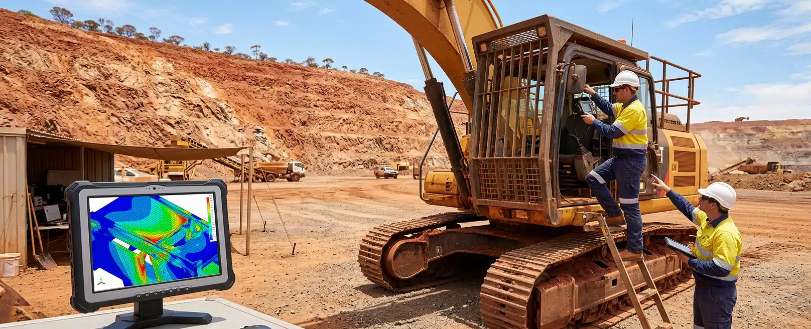
A ROPS and a FOPS are not the same canopy with two stickers. One holds a survival space if the machine rolls. The other keeps a falling object out of that space. Compliance starts when you name which job the structure must do, on which machine, and for which seated position.
Skip that and you can analyse the wrong load case, or fit a frame that never belonged on that class of plant. The engineering team brings the geometry, the load path and the installation evidence together with the engineering team so the file you take to a certifying party describes the structure that will actually be built.
Name the Protective Structure and Occupied Position
Rollover protective structures exist to keep a zone around the operator when the machine goes over. Falling-object protective structures exist to resist an impact from above without letting the object into that zone. Many mining machines need one, the other, or a combined arrangement. Those are still two performance problems, not one generic cage.
Write down the occupied seat you are protecting. ISO 3471 for metallic ROPS applies to listed earth-moving machines with a seated operator and a mass of 700 kg or more: dozers, loaders, backhoe loaders, dumpers, pipelayers, the tractor section of a combination machine, graders, landfill compactors, rollers and trenchers. It does not apply to training seats or extra seats used only to run an attachment.
ISO 3449 sets laboratory tests for FOPS on ride-on earth-moving machines as defined in ISO 6165. It is not applicable to FOPS on landfill compactors, excavators, rollers, trenchers or pipelayers, nor to an extra attachment seat, nor to machines rated below 15 kW.
Which Hazard the Canopy Must Survive
If the live risk is a roll on a dump or a grade, you are specifying ROPS behaviour. If the live risk is rock, spoils or dropped components from above, you are specifying FOPS behaviour. A combined canopy can address both, but only if each performance requirement is stated and then tested or analysed on its own terms.
Do not treat mass as a shortcut. The 700 kg figure in ISO 3471 is an applicability floor for those listed machines, not a rule that lighter vehicles follow a different mining ROPS recipe. If the asset is not in that earth-moving list, you still have to find the standard that actually covers it.
Combined Structures and Extra Occupancy
A second person on an attachment seat sits outside the ISO 3471 ROPS specimen for the primary operator. FOPS supplied with the machine and FOPS attached later are both in the ISO 3449 laboratory scope, provided the machine type is in scope. Specify whether the structure is integral or an add-on. That choice changes mounts, load paths and how you prove the connection into the frame.
Match the Machine to the Laboratory Test Route
Compliance is a nominated standard, a representative specimen and a test method, not a drawing note. ISO 3471 evaluates metallic ROPS by laboratory testing with static loading on a representative specimen. That is a controlled, repeatable laboratory method. It is not a filmed full rollover sequence, and it does not begin until you have named the right specimen.
ISO 3449 specifies laboratory tests that measure structural characteristics of FOPS and sets performance requirements in a representative impact test. The object, the drop and the acceptance criteria live in that laboratory method. If your machine type is excluded from ISO 3449, that impact test is the wrong destination no matter how similar the canopy looks.
What a Certifying Party Actually Needs
A certifying party works from the standard you nominate, the specimen you present, and the evidence that the built structure matches that specimen. The engineering team prepares calculations, models and installation records for that file. The certificate still comes from the party that owns the test and the approval, not from the analysis alone.
Physical testing on a representative specimen remains the evaluation method those ISO texts describe. Analysis can cut wasted prototypes, expose weak joints early, and document how the design is expected to behave under the stated load cases. You still complete the laboratory method the standard actually calls up.
What Finite Element Analysis Adds to a Certification File
The engineering team uses finite element analysis to predict how a structure responds to defined forces before you cut plate or book a laboratory slot. It quantifies stress, deflection, vibration and thermal behaviour so geometry and materials can be refined for strength, weight and cost. For protective structures, the useful output is traceable evidence against the load cases you have specified.
Typical studies include linear and nonlinear static work, modal and harmonic response, transient and impact cases, thermal and thermo-mechanical coupling, buckling and fatigue. Best practice is realistic load cases, accurate material data, sound meshing and contact with convergence checks, correlation with tests, and documented assumptions. That last item is what a reviewer can interrogate.
Static Load Cases Versus a Rollover Film
For a ROPS discussion aligned with ISO 3471, the analysis should follow the static laboratory load cases, not an invented full rollover animation. Watch deflection at the points that define the protective zone. Watch stress at posts, beams, welds and mounts. If a joint sheds load into a thin cab skin, the model should show that path so you can change the joint before anyone welds it.
For a FOPS discussion aligned with ISO 3449, impact cases estimate deformation, penetration risk and the demand on the attachments. The laboratory impact test is still the performance method in that standard. The model is how we decide whether the canopy and its mounts are ready to be tested, and how we record the assumptions behind that decision.
Documentation Reviewers Can Follow
A usable FEA pack shows mesh quality, material properties, boundary conditions, applied loads and results for every required load case. It should also state what was not modelled, including weld process, corrosion allowance or a mount that still exists only as a concept. Material certificates, weld procedures and fabrication checks then have to match the analysed configuration.
If the shop changes a post size or a base plate, the file no longer describes the specimen. Keep the as-built configuration with the analysis, including weld maps and a test record of critical fasteners.
Root-cause modelling after a field failure is a different job from first certification. The engineering team can reverse a load path under the assumed forces, material data and boundary conditions to test a hypothesis for how a crack started. Use that result to decide the repair on that machine, then reassess sister units on their own evidence.
Load Paths, Visibility and Access on the Real Machine
The structure has to take laboratory or impact load into the frame without punching a local hole in the chassis. Mounting points, gussets and the cab interface are part of the protective system. If those connections are an afterthought, the canopy can look heavy enough and still fail the machine it sits on.
Weight is a stability question as well as a steel question. Extra mass high on a loader or dozer moves the centre of gravity. The engineering team looks at mounting locations and frame integration so the protective duty does not quietly create a different handling problem. Member size and grade follow the load case and the fabrication route you can actually weld and inspect.
Sightlines, Sensors and Service Access
Posts and cross-members create blind spots. Place them where they hold the zone and still leave the operator a view of the work face, the hitch and the ground at the wheels or tracks. Cameras, lighting and detection gear for assisted or autonomous modes need a clear field of view. A canopy that shades a sensor or blocks a lamp has not finished its job.
Service access is the constraint that shows up on the first shutdown. Filler points, isolators, hydraulic banks and electrical cabinets still have to be reachable. If a beam lands on the only isolation point, you have protected the seat and made the machine harder to make safe for maintenance.
If the cab face, mounts and remaining structure are accessible, 3D scanning gives the as-built geometry so the model and the fabrication drawings are not guessed at a catalogue cab. A tray, guard or existing canopy that covers that face has to be moved, or the scan taken from an open side, before the measurement is useful.
Engineered Installations Group holds that process against the named asset.
Where Geometry, Mounts and Services Must Agree
Protective steel shares the machine with wiring, controls and, on some assets, battery hardware. The engineering team brings electrical engineering into that discussion when a harness, cabinet or control architecture has to pass through or around the structure without becoming the weak point in a crush or an impact. Cut lists and termination details fail if the loom is later drilled through a ROPS post.
When electrical and control hardware share the same envelope, system design is how the engineering team keeps mounts, harness routes and safety circuits in one package rather than discovering clashes after the canopy is already cut.
Cab mounts often have to do two jobs that pull against each other. Isolation mounts reduce vibration into the operator and into electronics. Structural continuity is what carries laboratory or impact load. The hardware and the connection details have to be designed for both, or you will get either a harsh cab or a mount that tears out when the canopy is loaded.
The engineering team uses vibration data analysis when the question is a repeating mechanical mode at a mount, a canopy stay or a cabinet bracket. That work supports dampening and mounting choices on rough terrain and variable load. Use it as condition evidence when you set dampening and inspection points on those mounts.
Modified Ute Load, Ride Height and Brakes
If the job is a modified Australian ute rather than earth-moving plant, vehicle category and integration still matter, and they are a different file. Braking and suspension upgrades are engineered for Australian utes under load.
A change in GVM, ride height or axle duty on a ute changes how that vehicle should be assessed as a modified vehicle. It does not certify a protective structure on a loader sitting next to it. Keep the ute pack and the earth-moving specimen in separate evidence trails.
Fitment Location Changes What You Can Verify
The analysed geometry only stays honest if the installed structure matches it. Fastener grade, weld placement, shim stacks and the order of assembly all change how load enters the frame. Treat installation as part of the evidence, not as a separate workshop story after the model is closed.
When the machine can be booked into Forrestdale, workshop installation gives controlled access to mounts, torque, clearances and the protective zone around the seat. Pre-fit checks catch a canopy that does not match the drawing. Post-fit checks catch interference with controls, doors, lamps and isolation points.
When the plant cannot come off site, on-site installation has to work around live operations, limited cranage and whatever access the pit or workshop bay actually allows. The same verification still matters. The structure that was modelled is the structure that was fitted, and you can still reach the isolation point after the last bolt is torqued.
Unauthorised holes, extra lamp brackets and cut-outs change load paths. The engineering team recommends an engineering review before those changes are treated as minor.
Inspect installed steel for impact damage, corrosion and fatigue at known concentrations. Record what you find. Condition monitoring can support that programme. Plan inspections around damage you can see and around known stress raisers.
Autonomous or remote operation does not automatically retire the canopy. People still climb on for recovery, maintenance and occasional manual modes. Specify those occupied positions if they exist. Keep sensor masts and antennae off the members that have to carry laboratory load unless those mounts were in the model.
The Practical Answer
Specify the protective structure by hazard and by occupied seat, then name the standard that applies to that machine type. For in-scope earth-moving ROPS, ISO 3471 points to static laboratory testing on a representative specimen. For in-scope FOPS, ISO 3449 points to a laboratory impact test.
Finite element analysis supports that route by producing traceable evidence, exposing weak load paths and recording assumptions. It supports certification. It does not replace the laboratory method.
If you want us to work from evidence rather than a generic canopy sketch, send the items below, then discuss the project with those details attached.
- Machine make, model, serial or plant number, and operating mass
- Whether the duty is ROPS, FOPS or both, and which seats are occupied
- The standard you believe applies, or the reason you are unsure
- Photographs or scans of the cab, mounts and any existing canopy
- Known frame modifications, extra brackets and electrical cabinets in the same zone
- Whether the machine can come to Forrestdale or must stay on site
- For a modified Australian ute only, current GVM, suspension and brake specification, kept separate from any earth-moving ROPS file



Leave A Comment