
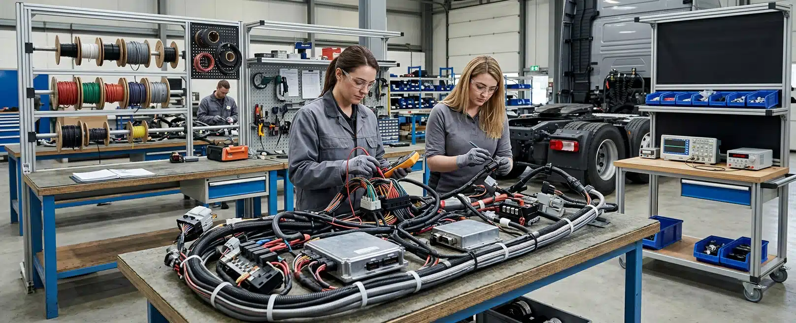
An auxiliary electrical job fails at the start if you treat every truck, machine and service vehicle as the same platform. The first decision is which requirements belong to that vehicle, that duty and that add-on. Then we assemble a pack that shows supply, load, routing and safety functions clearly enough for someone else to check.
The engineering team brings that work together at the engineering team as electrical design plus installation. Australian Design Rules sit in one column. Machinery electrical standards, functional safety methods, environmental tests and network practices sit in others. Mixing those columns is how a lighting loom, a PLC cabinet or a high-voltage harness gets specified against the wrong document.
Legal Applicability Comes Before Component Catalogues
The Australian Design Rules are national vehicle standards for safety, anti-theft and emissions. They apply to new vehicles manufactured in Australia and to imported new or second-hand vehicles being provided to the Australian market. From 1 July 2021 the Australian Government has determined ADRs under the Road Vehicle Standards Act 2018.
That is a market and construction rule for road vehicles. The OEM electrical architecture already in the chassis remains the starting point for any auxiliary circuit. ADR numbering also matters when you quote a rule. ADR X/00 is the original version. Later revisions such as ADR X/01 mark an increase in stringency, extra vehicle categories or a significant content change.
Record Category And Rule Version First
ADR 42 is listed among current Third Edition rules as General Safety Requirements, with published versions including ADR 42/04 and ADR 42/05. If a modification must remain a road vehicle under the ADRs, we treat the applicable rule versions and vehicle category as inputs, then design the electrical work so it can be assessed against those inputs.
Harmonisation ADRs exist to accept certain UNECE regulations that Australia has applied as alternative standards. That can change which international text is a lawful pathway for a given vehicle. Keep the legal question separate from the component question: what must this vehicle satisfy to be provided to the market, and what must this harness survive in service.
Australian electrical compliance for a heavy vehicle electrical system therefore starts with category and rule version, not with a parts catalogue. Quote the instrument that actually applies. Leave OEM, component and workshop practice in their own layer so a lighting circuit is not asked to prove a safety function it was never designed to perform.
Take A New Electrical Baseline After A Ute Duty Change
Australian ute braking and suspension upgrades are a light-vehicle mechanical package for that category of ute. They manage load, stopping and park-brake holding on those vehicles. After any mass or duty change on a ute, take a new electrical baseline for that vehicle only: battery condition, added loads and whether the new hardware needs its own supply and protection.
An electrically actuated secondary park brake is a new load on that ute. Specify its supply and protection in the schematic, and keep that circuit off lighting and other convenience taps.
Machinery Standards Answer A Different Electrical Question
When the asset is a machine or mobile plant rather than a series-production road truck, IEC 60204-1 applies to electrical, electronic and programmable electronic equipment of machines that are not portable by hand while working, including a group of machines working together. Coverage starts at the point of connection of the supply to the electrical equipment of the machine.
That standard is about the electrical equipment of the machine. IEC 62061 is a machinery-sector functional safety standard within the IEC 61508 framework. It specifies requirements for the design, integration and validation of safety-related control systems for those machines. It is concerned with functional safety intended to reduce the risk of hazardous situations from the machine or a coordinated group of machines.
Electrical hazards arising from the electrical control equipment itself sit with IEC 60204-1. IEC 62061 is the control-system safety job. If you are adding a cabinet, a drive or a control station to plant, name which of those two jobs you are actually doing.
ISO 13849-1:2023 specifies a methodology for the design and integration of safety-related parts of control systems, including software, for high demand and continuous modes of operation. It does not apply to low demand mode. It does not nominate the safety functions or required performance levels for a particular truck or excavator. Those required levels come from the risk assessment and, where they exist, from Type-C machinery standards.
ISO 14119:2024 covers principles for designing and selecting interlocking devices associated with guards, including trapped-key systems. The processing of the interlock signal to stop the machine and prevent unexpected start-up is pointed to ISO 14118, ISO 13849-1 and IEC 62061. ISO 13850:2015 specifies functional requirements and design principles for the emergency stop function, independent of the type of energy used.
Those documents tell us how to treat e-stops, interlocks and safety-related control parts on machinery. Road ADR clauses stay with the road vehicle they were written for. The electrical pack then follows the class of equipment you are actually modifying.
When the engineering team does electrical engineering for machinery, heavy vehicles and mobile equipment, the useful output is a schematic and harness pack that names the supply point, the loads, the safety circuits and the terminations. Ambiguous drawings are how assembly and fault-finding invent a second, unofficial design.
Safety Functions Need Their Own Architecture
An auxiliary controller that shares a casual earth or a convenience power tap with lighting is not a safety architecture. Mechanical mounting, power distribution and communication come together in system design so they are treated as one machine. The power and communication network has to be designed without harming the circuitry that already runs normal machine operations.
Safety circuits such as emergency stops and interlocks are designed as redundant safety functions against functional safety standards. That is a control-system decision. Feasibility work should define the functions, the performance needed and the early risks before anyone cuts cable.
Road Vehicle Functional Safety Is Not The Same Series
ISO 26262-1:2018 is the vocabulary part of the road-vehicle functional safety series. It is intended for safety-related electrical and electronic systems installed in series production road vehicles, excluding mopeds. It addresses hazards caused by malfunctioning behaviour of those systems, including interaction between them.
It does not address electric shock, fire, smoke, heat, radiation, toxicity or similar hazards unless those events are caused directly by malfunctioning E/E behaviour. Unique systems on special vehicles, including systems designed for drivers with disabilities, sit outside that stated scope. If your asset is a series road vehicle, ISO 26262 language may belong in the pack. If it is a mobile mining plant, the machinery functional safety set above is usually the closer fit.
Name the hazard, the function that reduces it, and the standard series that actually covers that class of equipment. A telematics install does not inherit a SIL or a performance level from the word safety on a brochure.
Environment And Networks Govern What Survives On The Vehicle
Legal rules decide whether a vehicle may be provided to the Australian market. Environmental and network documents decide whether the electronics still work after heat, shock, dust and other traffic on the bus. ISO 16750-1:2023 applies to electric and electronic systems and components for vehicles, including electric propulsion systems with maximum working voltages according to voltage class B.
It describes potential environmental stresses and specifies tests and requirements for the mounting location on or in the vehicle. It is not intended for motorcycles and mopeds. Electromagnetic compatibility is not covered by that document. Location on the chassis therefore belongs in the requirements list. Cab, chassis rail, engine bay and implement all see different stress.
SAE J1455 is a recommended practice for environmental conditions that influence electronic equipment on heavy-duty on and off road vehicles, and on stationary applications that use vehicle-derived components. Examples in its scope include on and off highway trucks, trailers, buses, construction equipment and agricultural equipment including implements. It is recommended practice, not an Australian legal instrument.
SAE J1939 is a recommended practice for the serial control and communications network used on heavy-duty vehicles. The top-level document is an overview. It describes the subordinate document structure and defines terms and abbreviations used across that family. When an auxiliary device must talk to engine, transmission or body controllers, J1939 compatibility is a network requirement, not proof that the install meets an ADR.
The engineering team uses vibration data analysis when the question is how the real machine moves at the proposed mount. A baseline signature at the mount location is more useful than a generic harsh-environment label. Use that signature to decide whether the proposed mount is acceptable for the component you intend to fit.
The engineering team uses finite element analysis when the question is structural: a bracket, a battery enclosure, a frame cut or a set of fasteners under dynamic load. FEA can supply traceable evidence against structural safety standards such as ROPS and FOPS performance requirements. ISO 3471:2008 covers metallic roll-over protective structures for specified earth-moving machines. ISO 3449:2005 covers falling-object protective structures for ride-on earth-moving machines, with stated exclusions.
Engineered Installations Group holds that process against the named asset.
Geometry Decides Whether The Harness Can Be Built
A schematic that ignores the tray, guard or tank you will actually hit will be redrawn on the floor. 3D scanning is useful when the engineering team needs the as-is geometry before we lock harness routing, gland positions and isolation access. Scan data does not choose the standard. It stops us designing a loom for a vehicle that no longer matches the brochure.
Cable sizing, voltage drop, bundling, heat and abrasion protection remain engineering judgements for the run you are actually installing. A run that is adequate for current can still starve a load at the far end of a prime mover. A loom through a hot compartment needs different derating from a short cabin drop. Protection should sit so that a fault isolates the affected branch without killing unrelated machine functions.
Connector choice follows current, sealing, vibration and service access. A rating that looks comfortable on a bench can be marginal on a rail that sees mud, wash and continuous shake. Record the part, the ingress protection you are designing to, and why that location was accepted.
Isolation Access Is Part Of The Electrical Design
Work on plant that can start or release stored energy is a known injury pattern. Victorian plant guidance is that employers must isolate, de-energise, lock out and tag out plant before maintenance or repairs. Isolation procedures should identify every energy source that could re-activate the plant, including electricity from mains, solar and generators, plus hydraulics, pneumatics and stored energy.
Emergency stop buttons, lanyards and similar devices are not satisfactory isolation points on their own. They are not designed as everyday isolators, cannot always be locked, and may leave control circuits live. The design pack should show isolation points that a competent person can lock. It should not hide those points behind a tray or a gland plate that cannot be reached in the field.
Your isolation procedure still governs the work. The job is to make the electrical layout compatible with those rules: labelled isolators, documented energy sources, and drawings that match the machine.
Workshop Or Field Changes What You Can Prove
A design that cannot be inspected where the vehicle lives is only half a pack. Vehicles that can be booked into the bay suit workshop installation at Forrestdale, where access to the loom, controlled isolation and pre and post-install checks are easier to complete.
When the machine cannot come in, on-site installation is the path, from a single-unit fit-out to a longer site programme. Choose the location for access and verification, not for a preferred postcode.
If glands, earth points and safety devices will be buried after cladding goes back on, photograph and record them before they disappear. Commissioning still has to show that the added system does not disturb the circuits that already run the vehicle.
Assemble The Pack Before Anyone Cuts Cable
Select requirements first, then freeze the design. The drawings, cut lists and test records then have to show the supply, loads, routing, mounts and safety functions that belong to that freeze.
Useful contents of the implementation pack are:
- System requirements, energy sources and isolation points
- Schematics with supply, loads, protection intent and safety functions
- Harness cut lists, material BOM and termination instructions
- Routing or scan-derived clearances where geometry is tight
- Mount load cases and vibration notes where brackets or enclosures take abuse
- As-built mark-ups and test records after commissioning
Photograph routing before sleeving hides it. Record part numbers as they go in. If the field changes a gland or a fuse rating, the as-built schematic has to change with it. A drawing that no longer matches the vehicle is not evidence.
What This Means For The Next Install
The practical answer is to name the vehicle class and the duty, pick the legal instrument and the technical series that actually apply, then design the auxiliary system so supply, load, routing, mounts and safety functions can be checked from one pack. A machinery SIL, a ute brake kit and a network recommended practice each answer a different question.
If you want us to discuss the project, send:
- Vehicle or plant identification
- What you want to add and where it will mount
- The existing schematic or OEM electrical information you have
- Any site rule that governs isolation and commissioning
The engineering team uses those details to prepare an engineering and installation discussion. The inspection and the drawings still decide the work.



Leave A Comment