
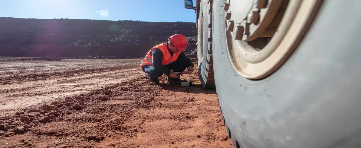
Heavy mining vehicles operate under some of the most punishing conditions in industrial applications. Wheel ends and final drives bear extraordinary loads, endure thermal cycling from extreme braking events, and accumulate operating hours at rates that would destroy conventional automotive components in weeks. When these critical drivetrain elements fail, the consequences extend far beyond a single vehicle — production targets slip, maintenance schedules cascade, and unplanned downtime costs can reach significant figures per hour.
Vibration data analysis offers a window into the mechanical condition of these components before visible damage appears or audible warnings emerge. By capturing and interpreting the characteristic frequencies generated by rotating assemblies, maintenance teams can detect bearing degradation, gear tooth wear, and misalignment issues while components remain serviceable. This diagnostic approach transforms maintenance from a reactive scramble into a planned, cost-effective operation.
Why Wheel Ends and Final Drives Require Specialised Monitoring
Failure Modes That Standard Inspection Methods Miss
Wheel ends on haul trucks, loaders, and dozers support vehicle weights measured in hundreds of tonnes whilst managing traction forces, braking loads, and impact events from rough haul roads. Final drives transmit engine torque through reduction gearing to the wheels, operating continuously under high loads and temperatures that would overwhelm passenger vehicle drivetrains within hours.
Common failure modes in these assemblies include bearing race spalling, roller element pitting, gear tooth micro-cracking, and seal degradation leading to lubricant contamination. Traditional inspection methods — visual checks, temperature monitoring, and oil sampling — often miss early-stage deterioration. By the time a technician hears abnormal noise or feels excessive play, damage has typically progressed beyond simple bearing replacement to require complete assembly rebuilds. At that stage, on-site installation support is often required to carry out the more extensive rebuild work at the vehicle’s remote operating location.
How Vibration Monitoring Fills the Diagnostic Gap
Vibration monitoring fills this diagnostic gap. Bearings and gears generate distinct vibration signatures as they rotate, and these signatures change predictably as wear progresses. A healthy bearing produces low-amplitude vibration at specific frequencies determined by its geometry and rotational speed. As surface defects develop, additional frequencies appear and amplitudes increase — often weeks or months before other symptoms manifest.
The Physics Behind Vibration Signatures in Drivetrain Components
Rolling Element Bearing Defect Frequencies
Every rotating component generates vibration at frequencies determined by its physical characteristics and operating speed. For rolling element bearings, four primary defect frequencies exist: outer race defect frequency, inner race defect frequency, rolling element defect frequency, and cage frequency. These frequencies depend on bearing geometry (number of rolling elements, contact angle, pitch diameter) and shaft speed.
When a defect develops on the outer race, each rolling element strikes the damaged area once per revolution of the cage, generating impacts at the outer race defect frequency. Inner race defects produce impacts at a different frequency because the inner race rotates with the shaft. Rolling element defects create vibration at twice the rolling element spin frequency as each defect contacts both races per revolution.
Understanding these relationships allows analysts to distinguish between normal operational vibration and developing faults. The amplitude growth rate over successive measurements predicts remaining service life — rapid harmonic development at 2x, 3x, and 4x fundamental frequency indicates accelerating damage requiring urgent intervention. Finite element analysis can complement this by modelling the stress concentrations in mounting structures that influence how vibration transmits from the defect source to the sensor.
Gear Mesh Frequency and Sideband Patterns
Gear mesh frequency equals the number of teeth multiplied by rotational speed. Healthy gears produce vibration primarily at mesh frequency and its harmonics. Tooth wear, misalignment, or cracking introduce sidebands around the mesh frequency — additional peaks spaced at shaft rotational frequency intervals. The pattern and amplitude of these sidebands reveal the nature and severity of gear degradation.
Planetary gear monitoring in final drives requires specialised analysis because planetary gear sets produce complex vibration signatures from multiple gear meshes occurring simultaneously. Separating these overlapping frequencies isolates individual gear stages and enables precise fault localisation within the assembly.
Data Collection Methodology for Mining Environments
Sensor Selection and Mounting Location
Effective vibration data analysis begins with proper sensor selection and placement. Accelerometers used in mining applications must withstand shock loads, temperature extremes, and contamination from dust and moisture. Industrial-grade triaxial accelerometers with stainless steel housings and hermetically sealed internals provide reliable operation in these conditions.
Sensor mounting location critically affects data quality. For wheel end monitoring, mounting positions on the spindle housing or suspension components provide the most direct vibration path from bearings. Final drive monitoring typically uses mounting points on the housing near the ring gear or pinion bearings. Magnetic mounting bases offer convenient attachment but introduce compliance that can attenuate high-frequency signals; stud mounting provides superior signal fidelity for permanent monitoring installations.
Sampling Rates, Collection Duration, and System Integration
Sampling rate must exceed twice the highest frequency of interest — typically 20 to 40 kHz for bearing defect detection in mining vehicle drivetrains. Data collection duration should capture at least 10 shaft revolutions to ensure adequate frequency resolution in the resulting spectrum. For components operating at low RPM, this requires longer sample durations.
Electrical engineering solutions often incorporate vibration sensors into broader condition monitoring systems, integrating data from temperature probes, pressure transducers, and oil quality sensors to provide comprehensive drivetrain health assessment.
Interpreting Vibration Spectra for Drivetrain Components
FFT Analysis and Bearing Diagnostics
Frequency domain analysis transforms time-domain vibration signals into spectra showing amplitude versus frequency. Fast Fourier Transform (FFT) algorithms perform this conversion, revealing the individual frequency components buried in complex waveforms. Analysts examine these spectra for peaks at known defect frequencies and evaluate amplitude trends over time.
Bearing diagnostics focus on identifying peaks at calculated defect frequencies. A peak at outer race defect frequency with amplitude exceeding baseline by a meaningful margin suggests early-stage damage. As wear progresses, harmonics appear at 2x, 3x, and 4x the fundamental defect frequency. The pattern of harmonic development provides prognostic information — rapid harmonic growth indicates accelerating damage requiring urgent intervention.
Gear Analysis and Envelope Analysis
Gear analysis examines mesh frequency and surrounding sidebands. Healthy gears show a strong peak at mesh frequency with minimal sidebands. Tooth wear introduces sidebands spaced at shaft frequency intervals. Misalignment produces sidebands at 1x and 2x shaft speed. Cracked teeth generate impact energy distributed across a broad frequency range, appearing as elevated noise floor rather than discrete peaks.
Envelope analysis enhances detection of early-stage bearing faults. This technique filters the signal to isolate high-frequency impacts, then demodulates to reveal the repetition rate of those impacts. Bearing defects produce periodic impacts that envelope analysis emphasises, making subtle faults visible before they appear in conventional spectra. EIG’s vibration data analysis service applies envelope analysis as standard for wheel end and final drive monitoring programmes.
Planetary Gear Monitoring in Final Drives
Final drive planetary gear monitoring proves particularly valuable for the compact, high-reduction gearboxes common in mining vehicle drivetrains. These assemblies operate at extreme torque levels and generate complex vibration signatures from multiple gear meshes occurring simultaneously. Specialised analysis techniques separate the overlapping frequencies to isolate individual gear stages, enabling precise fault localisation within the assembly.
Modern data acquisition systems capture not just vibration amplitude and frequency, but also phase relationships between measurement points. Phase analysis reveals misalignment conditions and load distribution issues that amplitude-only measurements miss. A final drive showing high vibration at both input and output bearings with consistent phase suggests a housing resonance; the same amplitude with 180-degree phase difference indicates internal misalignment.
Integration With Maintenance Planning
Vibration Trending and Three-Tier Alarm System
Vibration trending establishes baseline signatures for each monitored component and tracks changes over weeks or months. Initial measurements on new or freshly rebuilt assemblies define the healthy signature. Subsequent measurements at regular intervals build a trend database showing amplitude evolution at key frequencies.
A three-tier alarm system works well for mining applications. Advisory level prompts increased monitoring frequency. Alarm level schedules component replacement at next convenient shutdown. Critical level requires immediate action to prevent catastrophic failure. System design for fleet-wide monitoring programmes must address data management, analysis workflow, and integration with maintenance management systems.
The Economic Case for Wheel End and Final Drive Monitoring
The economic case for vibration monitoring rests on comparing programme costs against avoided failures. Unplanned wheel end or final drive failure causing extended downtime on a high-output haul truck can incur significant lost production costs in addition to emergency repair expenses. Preventing even a small number of such failures annually typically justifies the monitoring investment for fleets of meaningful size.
Field Implementation Challenges and Solutions
Remote Site Environment and Technician Training
Remote mining sites present unique challenges for vibration monitoring programmes. Temperature extremes affect sensor performance and data quality — accelerometers rated to appropriate temperature limits prevent thermal degradation in final drive housings that routinely exceed 100°C during operation. Dust ingress can compromise sensor connections; IP67-rated connectors with positive sealing prevent contamination.
Technician training determines programme success. Personnel must understand proper sensor mounting techniques, recognise invalid data from loose sensors or electrical interference, and perform basic spectrum interpretation to identify urgent issues requiring specialist analysis. Cloud-based platforms enable field technicians to upload data via mobile networks, with automated processing flagging anomalies for review by specialists located elsewhere. This distributed workflow allows expert analysts to support multiple sites without continuous travel.
Workshop Retrofit and Permanent Installation
Workshop installation services can retrofit vibration sensors and data acquisition systems to existing vehicles during scheduled maintenance intervals, minimising production impact. Permanent sensor installations eliminate mounting variability and enable automated data collection triggered by vehicle operating conditions.
Drivetrain diagnostic tools used during depot-based testing during scheduled services can catch developing faults before vehicles deploy to remote locations. This approach particularly suits operations where vehicle downtime location matters as much as frequency — a breakdown far from the nearest workshop carries costs far exceeding the same failure occurring on-site.
Autonomous Operations and Future Monitoring Integration
Condition Monitoring for Unmanned Mining Vehicles
The mining industry’s shift toward autonomous and semi-autonomous vehicle operations increases reliance on condition monitoring systems. Unmanned haul trucks cannot depend on operator vigilance to detect developing mechanical faults — automated systems must provide that awareness. Vibration monitoring integrated with vehicle control systems can trigger automatic speed reduction or route diversion when critical thresholds are exceeded, preventing catastrophic failures in unmanned operations.
Drivetrain Diagnostic Tools and the Path to Automated Analysis
The future of vibration monitoring in mining applications points toward fully automated analysis using machine learning algorithms trained on component life cycles. These systems will detect subtle pattern changes invisible to human analysts and predict remaining service life with greater precision than current threshold-based approaches. Integration with digital twin models of vehicle drivetrains will enable physics-based prediction of failure progression rates under actual operating loads.
Engineered Installations Group brings expertise in integrating condition monitoring systems into heavy mining vehicles, from sensor selection and installation through data analysis and maintenance planning support. Effective vibration data analysis requires understanding of machine dynamics, signal processing, and failure modes specific to heavy mining applications — wheel end bearings and final drive gears experience wear patterns unique to mining duty cycles that generic approaches developed for industrial machinery often miss.
Conclusion
For mining operations seeking to implement or expand vibration monitoring programmes, vibration data analysis provides the diagnostic foundation for condition-based strategies. The technology has matured into proven, field-ready systems that deliver measurable improvements in availability and maintenance cost efficiency. Success requires commitment to proper implementation — quality sensors, trained personnel, and systematic data management — but the operational benefits justify that investment many times over.
Call +61 (08) 9419 7318 to discuss vibration monitoring solutions tailored to your fleet’s specific requirements and operating conditions.



Leave A Comment