
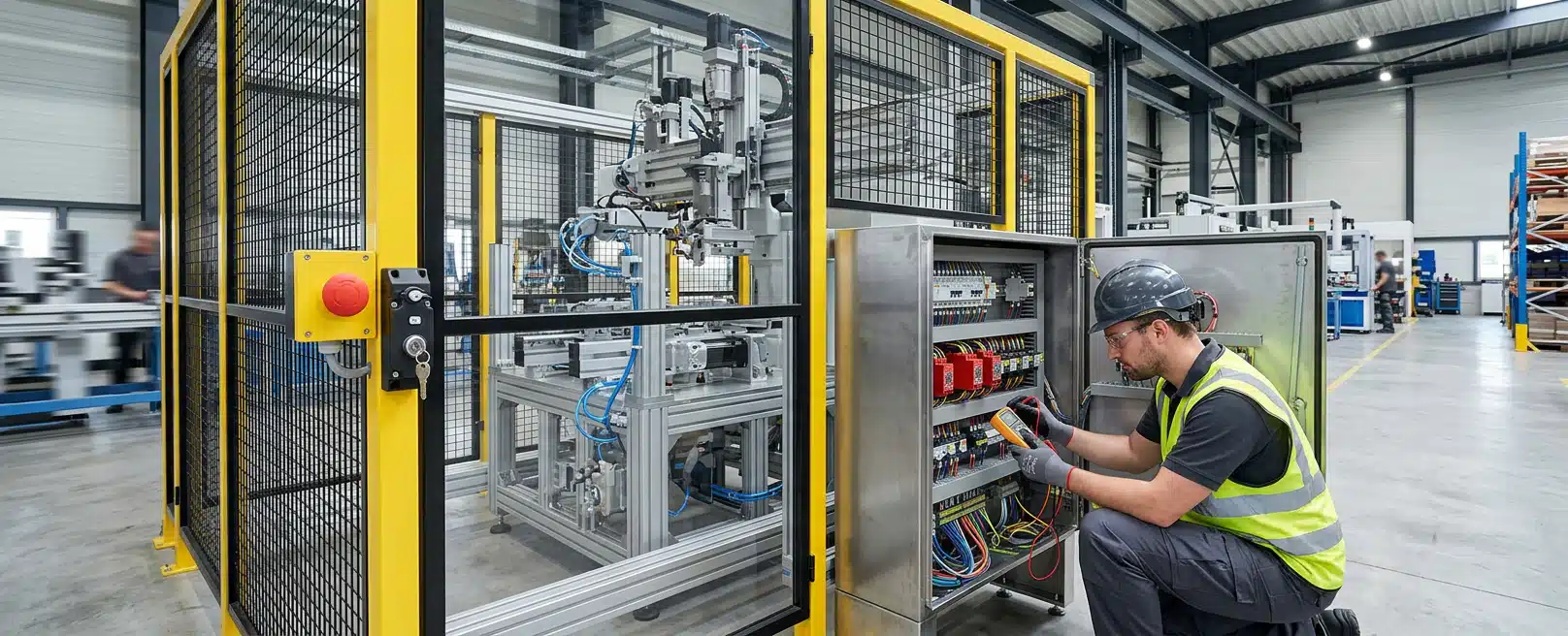
An emergency stop and a guard interlock protect people only when each one is defined as a safety function, not as a device on a panel. The function says which motion must cease, which energy must be removed or held, what must not restart, and in which machine states that response is required. Until that statement exists, the standards collapse into a list of buttons and switches.
The engineering team starts with the hazard and the people who can reach it. A mill door, a conveyor nip, a hydraulic ram and a mobile plant service point each need their own function description. Copying a circuit from another machine skips the work that sets architecture, diagnostics and the evidence you will need for validation and maintenance.
The engineering team brings the mechanical layout and the control architecture together at the engineering team so a named function can be followed from the risk record through the schematic, the mount and the test record.
Define Each Safety Function In Writing
A safety function is the behaviour the control system must deliver to reduce a specific risk. Hardware is how you implement that behaviour. If you specify a mushroom head before you specify the stop, you have chosen an actuator, not a function.
Writing The Emergency Stop Function
ISO 13850 specifies functional requirements and design principles for the emergency stop function on machinery, independent of the type of energy used. Write that function so it stays available while the machine can still create the hazard, and so a deliberate reset is required before anyone treats the stop as cleared.
The written function should name the hazardous motions and energy sources that must be removed or contained. It should state the intended stop behaviour, including whether motion may run down before access is safe. It should also say whether reset may restore power without restarting motion, and list every actuator location that must achieve the same function.
Keep the emergency stop as a complementary protective measure. Keep guarding as the primary safeguard for the hazard zone, and write isolation for maintenance as its own procedure. Collapsing those jobs into one button leaves access control and isolation unfinished.
On a group of machines that work together, say whether one actuator must stop the coordinated group or only the local unit. IEC 62061 includes safety-related control systems used singly or in combination on machines working in a coordinated manner. If the feed must stop with the crusher, that is part of the function, not a later interlock afterthought.
Writing The Guard Interlock Function
ISO 14119 specifies principles for the design and selection of interlocking devices associated with guards, independent of the energy source. It also gives guidance on measures to minimise reasonably foreseeable defeat. The device on the door is only part of the function. The function is what the machine must do when the guard is open, opening, or not confirmed closed.
Write whether hazardous motion must be prevented until the guard is closed, whether opening the guard must issue a stop, and whether the guard must remain locked until run-down is complete. Closing the guard should not, by itself, start the hazardous function. WorkSafe Victoria describes that restart as a manual action through the operator controls after the guard is closed.
Where trapped-key interlocking is the right selection, say so in the function, including which keys release which energy or access. ISO 14119 covers trapped-key devices and the parts of the guards that actuate the interlock. Processing of the stop signal still belongs with the safety-related control system under ISO 13849-1 or IEC 62061.
Defeat resistance belongs in that same description. A spare key left in a lock, a jumper across a simple switch, or a guard that can be left ajar while the sensor still sees closed are design problems, not only site behaviour. ISO 14119 asks you to select and apply the device so reasonably foreseeable defeat is minimised.
Turn Risk Into Requirements Before You Draw The Circuit
Required performance is an output of risk assessment for that function on that machine. It is not a default rating for a sector, a haul route, or a class of equipment.
What ISO 13849 Leaves To The Application
ISO 13849-1:2023 specifies a methodology for the design and integration of safety-related parts of control systems that perform safety functions, including software. It applies to high demand and continuous modes of operation, across electrical, hydraulic, pneumatic and mechanical technologies. It does not apply to low demand mode.
ISO 13849-1 does not specify the safety functions or required performance levels that are to be used in particular applications. You set those from the assessment of this machine, this access pattern and this task. Severity, exposure and the chance of avoiding harm belong in that assessment.
The engineering team uses that assessment to set the requirement the architecture must meet, rather than starting from a favourite category of circuit. Type-C machinery standards can add machine-specific requirements. If a relevant Type-C standard exists for the equipment, it should be read with the risk assessment, not instead of a function definition.
Component product standards still govern devices. ISO 13849-1 does not replace those either.
Where IEC 62061 Applies, And Where It Does Not
IEC 62061 is the machinery-sector standard for the design, integration and validation of safety-related control systems. It sits within the IEC 61508 framework and is concerned with functional safety that reduces the risk of hazardous situations arising from the machine itself. The main body addresses high and continuous demand.
Read IEC 62061 for functional safety of the safety-related control system. Read IEC 60204-1 for electrical hazards from the control equipment itself, such as electric shock. IEC 62061 also leaves machine-level safeguarding and security measures to their own documents. Treating a safety controller as a complete guarding solution, or as proof against shock, misreads the standard.
IEC 60204-1 applies to the electrical, electronic and programmable electronic equipment of machines, from the supply connection onward. Its control-circuit material includes emergency stop and related protection. We read it as the electrical equipment rules that sit beside the functional safety method, not as a second copy of the safety function.
For series production road vehicles, ISO 26262 addresses malfunctioning behaviour of electrical and electronic systems. That is a different framework from machinery emergency controls. Mixing the two vocabularies on a plant item usually hides an undefined function rather than strengthening it.
Keep Emergency Stop Separate From Isolation And Lockout
Emergency stop is a safety function that must stop hazardous motion and leave the machine in a safe condition. Isolation, de-energising, lockout and tagout are how you make plant safe to inspect, repair, maintain or clean. WorkSafe Victoria treats emergency stop buttons, lanyards and similar stop devices on their own as unsatisfactory isolation points.
Those devices are built for the emergency-stop function. They cannot be locked out in all cases, and they may leave control circuits live. Treat a tag as information for other people at the workplace. Use a lock on a true isolation point to prevent re-energising while someone is in the danger zone.
The engineering team recommends that the isolation scheme be written as its own procedure for the machine in front of us. Identify every energy source, including stored hydraulic, pneumatic, gravity and electrical energy. Identify isolation points, de-energise stored energy, lock and tag, then test before work.
Interlocked guards sit in a different place again. An interlock is a barrier connected to the power or control system so the guarded hazard cannot run unless the guard is closed, and so opening the guard issues a stop. Where moving parts take time to come to rest, the interlock may need to keep the guard locked until that risk has gone.
Isolation for a person inside the guard still needs lockable isolation points, not only the door switch. The door function controls access during operation. The isolation points are what you lock before someone enters the hazard zone to inspect, repair or clean.
Architecture That Can Be Built, Mounted And Tested
Once the function and the required performance are stated, architecture is the arrangement of devices, channels, diagnostics and mechanical parts that must deliver that function. Redundancy is useful only when both channels implement the same defined stop or interlock, and when faults are detected in the way the requirement needs.
Two channels that share one mount, one cable tray and one power feed still share common causes. Diversity of routing and of physical support is part of the architecture, not decoration on the drawing.
Tracing The Function Through The Schematic
The engineering team uses system design to hold the mechanical and electrical decisions in one package. That includes power distribution that does not starve or bypass the safety circuit, communication architecture, and emergency control systems such as redundant emergency stops and interlocks intended to meet functional safety standards.
Engineered Installations Group holds that process against the named asset.
The work moves from requirements and initial risk assessment, through detailed schematics and routing, into documentation for manufacture, installation and later certification by the parties who own that duty.
The electrical engineering work is the schematic and harness pack: layouts, cut lists, materials and termination instructions. Ambiguity in a safety circuit shows up as a jumper in the field or a spare core that nobody can explain. A clear schematic is evidence for validation and later fault-finding, not only a drawing for assembly.
Parametrization of programmable safety logic should be treated as part of the configuration, not as a local tweak. IEC 62061 includes requirements on parametrization and on periodic testing. If a parameter changes the function, the change belongs in the configuration record with the same discipline as a wiring change.
Checking Mounts, Alignment And Reach
A correct circuit still fails if the actuator cannot be reached, the guard does not drive the interlock, or vibration shears a switch bracket. Physical integration is part of functional safety because the function is delivered by parts that live on the machine.
The engineering team uses finite element analysis when the question is whether a mount, bracket, enclosure or frame can take the load cases, shock and fatigue of the duty. That includes checking field modifications and the integrity of control-gear mounts. FEA can also support structural evidence against standards such as ROPS or FOPS.
Treat ROPS and FOPS as protective-structure questions, and keep the emergency-stop rating and the interlock function on their own requirements. A cab structure that meets a roll-over test still needs a separately defined stop and interlock if people can reach hazardous motion.
The engineering team uses vibration data analysis when a repeating mechanical mode, imbalance or rough-terrain input may be working on the same mounts. Sensitive electrical components need mounting and damping that match that environment. A switch that chatters or a connector that works loose is a functional safety problem even when the schematic is correct.
The engineering team captures accessible surfaces, guard-to-device clearances and alignment with 3D scanning. If a tray or body panel covers that geometry, move it before the scan. Interlock actuation depends on alignment between the guard and the device. Guessing that gap from a photograph is how defeat paths and nuisance trips both appear.
Physical parts only deliver the function if they act on the right energy. A machinery emergency stop must cease named hazardous motion and remove or hold machine energy. Secondary park-brake holding on an Australian ute is a vehicle control: it holds the vehicle under load through the brake system, not through a plant interlock or e-stop channel.
Where the work is an Australian ute, braking and suspension upgrades address load, fade and secondary park-brake holding on that vehicle. Specify each on the pack that owns that energy path so the test record matches the function.
Evidence For Design, Validation And Maintenance
Design evidence is the set of documents that show the function, the requirement, the architecture and the assumptions. Validation evidence is the set of tests that show the built system behaves as designed, including under foreseeable faults. Maintenance evidence is what keeps that behaviour true after wear, parameter changes and repairs.
Validation should exercise every defined function, not only the button nearest the panel. For an emergency stop, that includes every actuator, confirmation that the named motions cease, confirmation that reset does not auto-restart, and a record of stopping behaviour where run-down time matters for access.
For an interlock, that includes open, closed and, where used, locked states, plus a check against reasonably foreseeable defeat. Periodic testing belongs in the maintenance plan because diagnostics do not remain an unexamined property of the hardware. IEC 62061 includes periodic testing among its design concerns.
Test interval and method should follow the architecture you actually fitted, including whether faults are detected automatically or only when someone tries the function. A useful test record names the function, the configuration revision, the actuator or guard used, the result, and who accepted it. Without those fields, a later audit only proves that someone pressed a button on some date.
Where The Machine Is Installed Changes What You Can Verify
Access decides whether you can reach every emergency-stop actuator, observe every guard, and prove isolation points without inventing a second circuit. If the machine cannot come off site, on-site installation is how we fit, commission and check the system in the real layout, including commissioning with operations.
If the asset can be booked into Forrestdale, workshop installation lets us complete fit-out and pre- and post-install checks under workshop control, including isolation practice during the work. Either location still needs the same function list and the same test record. The difference is access, not a different safety standard.
Keep configuration, schematic revision and test results together. A later harness repair that bypasses a monitored channel can retire a safety function without anyone renaming it. Maintenance should restore the documented function, then re-test that function, not only confirm that the machine runs.
What To Send Before Design Or Install
Define each emergency-stop function and each guard-interlock function as a required behaviour, then collect the evidence that design, validation and maintenance will need. Architecture comes after that definition. Isolation and lockout stay on their own procedure.
Send the pack that lets us argue from the machine in front of us:
- Machine identity, duty and whether it is fixed plant or mobile equipment
- Each proposed emergency-stop function: motions to stop, actuator locations, reset and run-down behaviour
- Each proposed guard-interlock function: which guard, stop or lock behaviour, and known defeat concerns
- Energy sources and known isolation points, separate from emergency-stop devices
- Existing schematics, safety configuration and any previous test records
- Photographs or scans of actuator reach, guard geometry and proposed mounts
- Where the work must happen, site or Forrestdale, and who will own certification
With that pack the engineering team can discuss the project against the functions you need to prove, not against a catalogue of devices.



Leave A Comment