
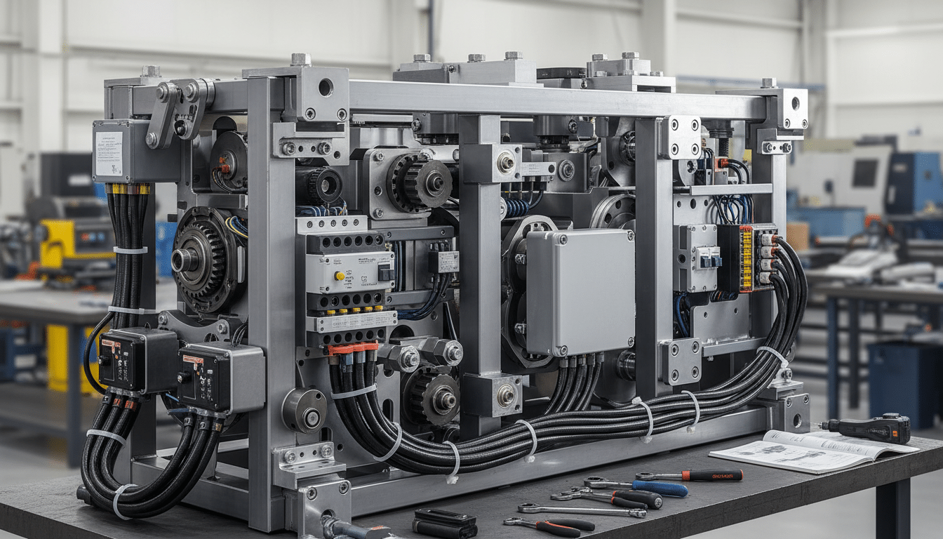
Mining operators and fleet managers face a persistent challenge: sourcing vehicle modification components from multiple suppliers creates coordination headaches, compatibility risks, and extended downtime. When mounting brackets arrive from one vendor, wiring harnesses from another, and control systems from a third, the integration burden falls on site teams who may lack the technical resources to troubleshoot conflicts between systems designed in isolation.
Kit design packages eliminate this fragmentation by delivering pre-engineered, installation-ready assemblies where mechanical, electrical, and integration components function as validated systems rather than disparate parts. This multidisciplinary approach reduces installation time, minimises compatibility issues, and provides single-point accountability for system performance.
What Makes a Complete Kit Design Package
A kit design package represents more than a collection of components shipped in the same box. It is a pre-engineered solution where mechanical hardware, electrical systems, and integration protocols have been designed concurrently, tested together, and documented as a unified system.
Beyond a Collection of Components
The mechanical elements include purpose-built mounting brackets, enclosures rated for specific environmental conditions, and structural supports validated through engineering analysis. These are not off-the-shelf brackets adapted to fit – they are designed specifically for the target vehicle platform and the loads imposed by the installed equipment.
Electrical components encompass custom wiring harness design that accounts for the vehicle’s existing electrical architecture, cable routing that avoids high-vibration zones and heat sources, and power distribution systems sized for actual load requirements. The harnesses arrive pre-terminated, labelled, and routed to match the mechanical layout.
Integration as the Differentiating Layer
Integration components tie the system together: control interfaces that communicate with the vehicle’s existing systems, mounting hardware that aligns electrical and mechanical elements, and testing protocols that verify functionality before the package leaves the assembly facility. The result is a mine-spec vehicle fitout delivered as a turnkey assembly package rather than a procurement puzzle. The site team receives a system that has already been proven to fit, function, and comply – not a set of parts that need to be reconciled on the vehicle.
The Mechanical Discipline: Structure and Physical Foundation
Creating effective multidisciplinary hardware kits requires expertise across mechanical engineering, electrical engineering, and systems integration. Each discipline contributes essential elements, but the real value emerges from how these specialisations collaborate during the design process.
Vehicle Platform Analysis and Bracket Design
Mechanical design establishes the physical foundation for every kit package. Engineers select materials based on the operating environment: aluminium alloys for weight-sensitive applications, stainless steel for corrosive conditions, or powder-coated mild steel for cost-effective solutions in controlled environments.
The design process begins with vehicle platform analysis. System design holds the mechanical and electrical interfaces in one model. Engineers measure mounting locations, identify load paths through the chassis, and determine clearance requirements for suspension travel and steering components. This data informs the design of mounting brackets that distribute loads appropriately without creating stress concentrations that lead to fatigue failures. Finite element analysis validates mechanical designs before fabrication, identifying potential weak points and allowing engineers to optimise bracket geometry for strength-to-weight ratio. The analysis considers static loads, dynamic forces from rough terrain, and fatigue life under cyclic loading conditions – all of which matter significantly on mining vehicles operating over rough haul roads.
Enclosure Ratings and Thermal Management
Enclosures for electronic components receive detailed attention. Ingress protection ratings match the exposure level: IP65-rated enclosures for equipment mounted in engine bays where pressure washing occurs, IP67 for components that may experience temporary submersion during water crossings. Thermal management features including heat sinks or ventilation slots prevent electronic failures in high-temperature environments. A control unit that operates within its thermal rating in a temperate climate may fail consistently when the same kit is deployed in a Northern Territory mining operation during summer.
The Electrical Discipline: Power, Signal, and Communication
Electrical design transforms power and signal requirements into reliable distribution networks that function consistently across years of operation in demanding conditions.
Schematic-First Design and Cable Specification
Custom wiring harness design begins with a complete electrical schematic mapping every power connection, ground point, and signal path. System design holds that schematic with the mechanical pack. This schematic becomes the reference document for fabrication, installation, and future maintenance. Cable selection considers multiple factors: current-carrying capacity for power circuits, shielding requirements for signal cables in electrically noisy environments, and insulation ratings for temperature exposure. Mining applications often specify cables with heavy-duty insulation that resists abrasion from rubbing against sharp edges during vehicle operation.
Routing strategy protects cables from mechanical damage and thermal stress. Harnesses follow paths that avoid high-vibration components, maintain clearance from exhaust systems and heat sources, and use existing grommets where cables pass through bulkheads. Where additional protection is required, engineers specify conduit or protective sleeving appropriate to the specific exposure. EIG’s electrical engineering solutions incorporate these routing and protection requirements as standard practice on every kit, not as optional additions reviewed at the end of the design process.
Connector Selection and Power Distribution
Connector selection balances reliability against serviceability. 3D services can lock connector positions before later kits are copied. Weatherproof connectors are commonly specified for exterior applications, while standard automotive connectors may suffice for protected interior locations. Connector keying prevents incorrect mating and ensures proper system operation when connectors are disturbed during maintenance.
Power distribution design accounts for the vehicle’s existing electrical capacity. Engineered Installations Group keeps that calculation with the kit pack. Engineers calculate total current draw, determine appropriate wire gauges and fusing, and identify suitable connection points in the vehicle’s electrical system. For installations that approach the alternator’s capacity, the design may include recommendations for electrical system upgrades before kit installation proceeds.
The Integration Discipline: Making the System Coherent
Integration engineering is meant to keep mechanical and electrical components working as one system. Vibration data analysis can show whether a newly mounted module is seeing more shake than the design assumed. This discipline addresses the interfaces between subsystems and the sequences that make installation practical.
Interface Design and Installation Sequencing
Integration addresses how the wiring harness routes through the mounting bracket assembly, where control modules mount relative to the sensors they monitor, and how installation procedures sequence to avoid rework. The integration process includes creating installation documentation that guides technicians through fitment step by step, specifying torque values for fasteners, identifying connection sequences that prevent damage to electronic components, and highlighting verification steps that confirm correct installation before the vehicle returns to service.
Pre-installation testing checks system function before the kit package ships. Vibration data analysis can show whether a newly mounted module is seeing more shake than the design assumed. Electrical circuits undergo continuity testing, power-on tests confirm that control systems initialise properly, and functional tests demonstrate that sensors, actuators, and control interfaces operate as designed. This testing occurs in a controlled environment where troubleshooting is straightforward, rather than on-site where diagnostic resources may be limited and production pressure exists. EIG’s workshop installation services provide the facility and tooling infrastructure that this level of pre-deployment validation requires.
Documentation That Supports the Full System Lifecycle
Documentation packages accompany every kit: as-built electrical schematics that reflect any field changes made during prototyping, mechanical drawings showing mounting locations and hardware specifications, and maintenance guides that identify service intervals and troubleshooting procedures. This documentation supports both initial installation and ongoing maintenance throughout the system’s service life. A technician working on the vehicle two years after installation should be able to open the documentation and understand exactly what was installed and how it was configured – without needing to contact the original installer.
From Concept to Installation-Ready Package
The development process for kit design packages follows a structured methodology that balances engineering rigour with practical installation considerations.
Initial Consultation and Cross-Disciplinary Design
Initial consultation establishes system requirements: what equipment needs installation, what vehicle platforms will receive the modification, what operating conditions the system must withstand, and what performance criteria define success. This conversation includes fleet managers who understand operational requirements, maintenance personnel who will service the installed systems, and procurement teams who manage budget constraints.
The design phase translates requirements into engineering specifications. Mechanical engineers model mounting solutions using CAD, creating three-dimensional representations that identify interference issues before fabrication begins. Electrical engineers develop schematics and specify components concurrently. Collaboration between disciplines occurs throughout: mechanical engineers consult with electrical counterparts to ensure enclosures accommodate the specified components with appropriate clearances, and electrical engineers coordinate with mechanical designers to route harnesses through bracket assemblies without creating pinch points or excessive bending radii.
Prototype Validation and Production Refinement
Prototyping validates the design before committing to production quantities. The first kit package undergoes installation on a representative vehicle, revealing any fitment issues, installation sequence problems, or documentation gaps that are not apparent in CAD models. This first-kit check happens at the Forrestdale workshop, where engineering support is available if a fit issue appears.
Design refinement incorporates lessons from prototype testing. If cable routing proves difficult during installation, the design is revised to improve accessibility. If a mounting bracket interferes with a service access point, engineers relocate the mount or redesign the bracket geometry. These refinements occur before production begins, ensuring that subsequent kits benefit from prototype learning. Where structural modifications are made during refinement, finite element analysis revalidates the revised bracket geometry before the change is committed to production. Final assembly of production kits follows documented procedures that ensure consistency across all units – technicians work from assembly drawings and checklists that specify component locations, fastener torques, and verification steps.
Why Multidisciplinary Packages Outperform Piecemeal Sourcing
Compatibility, Accountability, and Cost
The integrated approach to kit design packages delivers measurable advantages over sourcing components separately and managing integration on-site.
Compatibility issues disappear when a single engineering team designs all system components concurrently. There is less chance of buying a bracket that does not fit the selected module, or specifying a cable that does not mate with the supplied sensors. The multidisciplinary hardware kits approach inherently prevents these mismatches because every component was selected with awareness of every other component.
Accountability is simpler when one pack holds the mechanical and electrical parts. When issues arise, there is a single point of contact rather than multiple suppliers directing the client back to each other. Cost savings emerge from several sources: integrated design eliminates redundant engineering effort, bulk purchasing of components for multiple kits reduces unit costs, and reduced installation time lowers labour costs while minimising revenue loss from vehicle downtime.
Fleet Standardisation and Long-Term Supportability
When additional vehicles require the same modification, subsequent customized kits copy the first checked design rather than starting engineering from scratch. 3D services can lock the as-fitted bracket positions before the next kit is copied. This repeatability supports fleet standardisation initiatives that simplify training, parts inventory, and maintenance procedures. The same engineering methodology applies whether modifying light vehicles for field service applications or heavy mining equipment for autonomous operation.
Fleet managers seeking to standardise vehicle modifications across multiple sites benefit particularly from this consistency. Rather than each site developing its own approach to installing similar equipment, a validated kit package can be deployed across the fleet via on-site installation teams working from identical procedures and documentation. The value proposition becomes especially compelling for complex mine-spec vehicle fitout installations involving multiple subsystems – collision avoidance sensors, auxiliary lighting, communication systems, and power distribution upgrades – where coordinating these elements as separate projects multiplies complexity beyond what site teams can reliably manage. Contact us to check kit design requirements for the current fleet or modification program.



Leave A Comment