
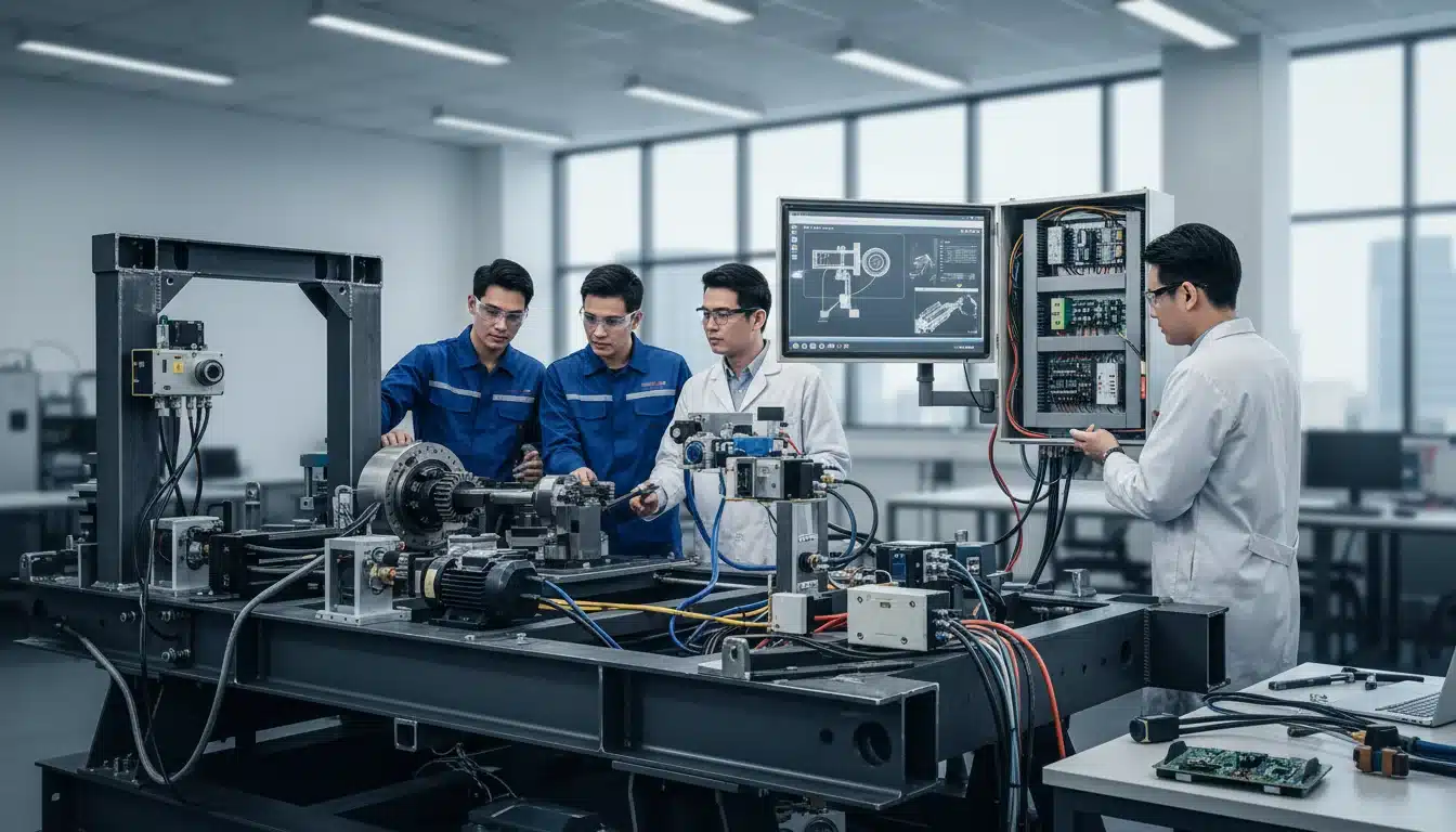
Heavy mining vehicles are not purely mechanical machines. They are electro-mechanical systems where hydraulic actuators respond to electronic control signals, where sensors mounted on structural components feed data to autonomous safety platforms, and where the routing of a wiring harness can determine whether a mounting bracket is accessible for field maintenance. Treating mechanical and electrical engineering as separate disciplines on these vehicles produces integration clashes that later cost time on the vehicle.
System design treats mechanical and electrical work as one job from the outset. Rather than completing mechanical design and then handing drawings to an electrical team, mechatronic design integrates both disciplines from initial concept through commissioning. For mining vehicles and heavy equipment operating in demanding environments, this approach is a practical way to keep both disciplines on the same constraints.
What Mechatronic System Design Actually Is
Mechatronic system design combines mechanical engineering, electrical engineering, and control systems into a unified design process. The boundaries between these disciplines are treated as interfaces to be managed, not handoffs to be negotiated after the fact.
Beyond Mechanical and Electrical in Isolation
In conventional project delivery, mechanical engineers design structures, mounting systems, and mechanical drive components. Electrical engineers then route wiring, specify power distribution, and integrate control systems into the mechanical design they receive. Problems emerge at this handoff point. Cable pathways conflict with mechanical access requirements. Mounting brackets occupy space needed for electrical enclosures. Vibration paths identified by mechanical engineers were not communicated in time to influence electronic component selection.
On a light vehicle mine-spec fitout, these conflicts are an inconvenience. On a haul truck integration involving autonomous mining safety systems, hydraulic control modifications, and fleet management hardware, they become costly rework and commissioning delays. The deeper problem is that neither discipline, working alone, has visibility of the complete system. Mechanical engineers optimise for structural integrity and maintainability without full awareness of electrical routing constraints. Electrical engineers route for signal integrity without understanding the mechanical loads their cable support structures must carry.
How EIG Applies Mechatronic Principles
EIG’s engineering approach treats mechanical and electrical design as concurrent activities governed by shared constraints. When a fitout project begins, the engineering team identifies where mechanical and electrical decisions are interdependent, and those interdependencies are resolved through joint design rather than sequential handoff.
Control system synchronisation receives attention from the outset. Whether the project involves integrating autonomous braking systems with existing hydraulic circuits, coordinating proximity detection sensors with vehicle speed controllers, or synchronising multiple lighting and alarm systems with operator interface displays, the control logic is mapped before physical design is finalised. That keeps the physical layout aligned with the control architecture rather than constraining it.
Why Sequential Engineering Fails on Mining Vehicles
The Handoff Problem
Sequential engineering: mechanical design completed, then electrical design applied, creates failure modes that are difficult to resolve without redesign. Wiring routed through zones identified as high-temperature by mechanical engineers after electrical routing was finalised must be rerouted, requiring bracket modifications and extended installation time. Mounting structures designed without awareness of electrical enclosure dimensions result in interference that only appears during physical installation.
These clashes show up on vehicle fitout programs when the disciplines are managed separately. In a workshop, rework is inconvenient. On a remote site, on-site field services still have to work inside shift and access windows, so a late clash costs time.
What Changes When Disciplines Collaborate From the Start
When mechanical and electrical engineers work from shared constraints rather than sequential drawings, the most common integration conflicts are addressed during the design phase. Cable pathways are routed with awareness of mechanical access requirements. Enclosure locations are determined with input from both structural load analysis and electrical layout requirements. Thermal management design accounts for heat generated by both mechanical and electrical systems in the same zones.
The result is a design that is easier to install as drawn and to check against the agreed commissioning list. Customized kits help keep later vehicles closer to that first agreed layout.
The Mechanical Side of Mechatronic Design
Structural Design That Accommodates Electrical Systems
Mechanical design in a mechatronic context is not simply structural optimisation. It is structural design that deliberately accommodates electrical system requirements. Mounting structures include provisions for cable entry and routing. Enclosure locations are determined through joint analysis of structural load paths and electrical layout requirements. Access panels and maintenance openings are positioned with awareness of both mechanical service requirements and electrical diagnostic access points.
Load analysis for equipment mounting considers the combined mass of mechanical and electrical components in the same zones. Finite element analysis can be used to check those mounts and brackets before steel is cut.
Vibration and Shock Isolation for Electronic Components
Mining vehicles can put electronics into vibration levels that exceed ordinary automotive ratings. Control units, sensors, communication modules and displays still need isolation from shock and vibration.
Vibration isolation design begins with a measured vibration spectrum at the proposed mounts. Vibration data analysis can feed that measurement into component and isolator selection. A control unit with a published vibration rating must be mounted on an isolation system tuned to keep input vibration within that rating across the vehicle’s operating speed and terrain range. Isolation mounts specified too soft allow excessive displacement; mounts specified too stiff transmit vibration that exceeds component ratings. Getting this right requires mechanical engineering input that is only available when mechanical and electrical design teams are working together.
The Electrical Side of Mechatronic Design
Power Architecture That Supports Mechanical Actuators
Mechanical actuators, electric motors, solenoid valves, hydraulic proportional controllers, create electrical load characteristics that differ from static electronic loads. Motor starting currents can be multiples of running current. Solenoid switching creates inductive voltage spikes. Proportional controllers draw variable currents that change with mechanical load.
Custom wiring harness design from Engineered Installations Group accounts for these dynamic load characteristics on complex electro-mechanical vehicles. Cable sizing calculations use peak current demand rather than steady-state values. Protection devices are selected for their response characteristics relative to the connected load. Power distribution architecture isolates actuator circuits from sensitive electronics to prevent the electrical noise generated by switching loads from corrupting sensor signals and control data.
Control System Synchronisation Across Actuators and Sensors
The synchronisation of control systems is meant to keep mechanical actuators responding to sensor inputs and operator commands in the right sequence, speed and tolerance. On mining vehicles with several interacting systems, poor synchronisation shows up as slow response, hunting or missed commands.
Consider a vehicle with autonomous speed control integrated with proximity detection. The proximity sensor detects an obstacle and commands a speed reduction. The speed controller receives the command and modulates the throttle. The brake system receives a secondary command if deceleration is insufficient. Each of these steps involves sensor signal transmission, control logic processing, and actuator response, each with its own latency. Synchronisation design is then checked so the combined latency of this chain can meet the required timing for the operating speed and detection range. Electrical engineering solutions that address signal integrity, grounding, and electromagnetic compatibility are foundational to achieving the timing performance that synchronisation requires.
EIG’s Mechatronic Design Process in Practice
Initial Assessment and Discipline Integration Planning
System design begins each project by assessing where mechanical and electrical disciplines are interdependent. This is not a generic checklist, it is a project-specific analysis of the fitout scope, the vehicle platform, the operating environment, and the performance requirements.
For a mine-spec vehicle fitout involving collision avoidance integration, structural modifications, and electrical system upgrades, the integration planning identifies every point where a mechanical decision constrains an electrical option, and vice versa. These interdependencies are documented before detailed design begins, ensuring that the mechanical and electrical engineers are working to shared constraints rather than discipline-specific optima.
Cross-Disciplinary Design Reviews
Design reviews at EIG involve mechanical engineers, electrical engineers, and installation technicians examining designs simultaneously. Each discipline reviews the others’ work for integration conflicts, not just for internal correctness. An electrical schematic that is technically sound may create a cable routing path that conflicts with a mechanical access requirement. A structural bracket that meets load requirements may occupy an enclosure location needed for electrical equipment.
Conflicts identified during cross-disciplinary reviews are resolved before fabrication. The resolution is documented, the affected drawings are updated, and the change is reviewed to confirm it does not create new conflicts in adjacent systems. This process takes more time in design than a sequential review. It is still cheaper than finding the same clash after fabrication.
Workshop Installation and Validation
The Forrestdale workshop gives a controlled place to install and test a mechatronic design. Workshop installation services support the first vehicle in a fleet program so later units follow a checked layout.
Pre- and post-installation QA checks verify that both mechanical and electrical aspects of the installation meet design specifications. Mechanical checks confirm mounting security, clearances, and structural integrity. Electrical checks confirm wiring integrity, system function, and control system synchronisation performance. The combination of both discipline checks on the same vehicle, at the same time, is what mechatronic quality assurance looks like in practice.
Mechatronic Design in Mining Applications
Mine-Spec Vehicle Fitouts With Complex Electro-Mechanical Requirements
Mine-spec vehicle fitout programs that involve simultaneous mechanical modifications and electrical system upgrades are where mechatronic system design and electro-mechanical integration deliver their most visible value. Adding autonomous safety systems, collision avoidance hardware, and fleet management equipment to a vehicle that also requires structural modifications, tow bar upgrades, and canopy additions creates a project where mechanical and electrical decisions are continuously interdependent.
Single-discipline subcontracting on these projects, separate mechanical and electrical contractors coordinating through drawing exchange, produces the integration failures described earlier. EIG’s mechatronic approach keeps those interdependencies inside one engineering team, so coordination gaps are less likely to generate rework.
Autonomous and Semi-Autonomous System Integration
Autonomous mining safety system integration is among the most demanding applications of mechatronic design. Positioning sensors must be mounted where mechanical structures provide adequate protection without obstructing sensor field of view. Actuator integration with existing hydraulic circuits requires mechanical modification and electrical control system design to proceed concurrently. Control system timing for autonomous operation should be checked against the installed hardware, not only the theoretical specification. 3D services can capture the as-fitted sensor and bracket positions used in that check.
Sensor-Actuator Coordination on Heavy Equipment
Electro-mechanical integration on heavy equipment involves sensor-actuator coordination across systems with different response characteristics. A load sensor on a hydraulic lifting system provides data to a control unit that commands a proportional valve. The valve modulates hydraulic flow that produces mechanical movement. Each step in this chain has its own response time, and the overall system performance depends on all steps being coordinated correctly.
Poor sensor-actuator coordination produces control instability, hunting, or slow response that reduces operational efficiency and, in safety-critical applications, creates risk. Mechatronic design addresses this through analysis of the full signal chain, from sensor characteristic through control logic to actuator response, then checks that chain against the required timing.
Why Mechatronic Planning Matters After Handover
Designing for Maintenance Access and Modification
Mechatronic designs are documented to support maintenance and future modifications across both disciplines. Electrical access points are not blocked by mechanical structures. Mechanical service requirements are not compromised by electrical installations that were routed without considering maintenance access. This discipline integration in documentation is as important as the engineering decisions that produced the design. Electro-mechanical integration that is well-documented supports maintenance and modification across the vehicle’s entire service life.
Engineered Installations Group can supply as-built documentation for a mechatronic installation: electrical schematics, mechanical drawings, control system configuration records, and QA test results, so later maintenance teams have a usable reference.
Quality Assurance Across Disciplines
Quality checks should cover the mechanical and electrical work in the same workflow, not as two isolated sign-offs. The workshop record should describe the system as fitted, not only each discipline in isolation.
For fitout programs or autonomous system integrations where mechanical and electrical work must be planned together, Contact us to check the current scope.



Leave A Comment